fillet again

Next
 From:  malvin
1807.1 
Hi
Please advice what I am doing wrong
I tried various shapes of ring – in each the circle edges after sweep fall apart thus I cannot fillet them.
In other cases one side is solid edge on the opposite – all broken

I did the curves smooth – are they not smooth enough?

How then do I do these shapes that are very common.

-Thanks - Olga-
Attachments:

  Reply Reply More Options
Post Options
Reply as PM Reply as PM
Print Print
Mark as unread Mark as unread
Relationship Relationship
IP Logged

Previous
Next
 From:  Michael Gibson
1807.2 In reply to 1807.1 
Hi Olga, maybe I don't quite understand, but I did not seem to have any problems filleting the first one that I tried:


That was with a radius of 0.5. Often times it is surprising how much area a fillet will take up, so it can be a good idea to keep going to a smaller radius value to see what will fit.

It's ok if the edges are broken up in multiple pieces, just select all of them.


The ring that is up above will probably be difficult to fillet except maybe with a very small radius, because it has a tight bend in the surface.

A fillet needs space to move a constant distance away from an edge. If you have a tight bend in the edge or the surface, it can limit the radius of fillet that can be used. Otherwise it would cause the fillet to bunch up, here is an illustration of this problem:


Just to make sure, have you seen some of Jesse's tutorials on making ring shapes? They may be helpful:

http://moi3d.com/forum/index.php?webtag=MOI&msg=284.1
http://moi3d.com/forum/index.php?webtag=MOI&msg=510.5
http://moi3d.com/forum/index.php?webtag=MOI&msg=623.1
http://moi3d.com/forum/index.php?webtag=MOI&msg=556.1
http://moi3d.com/forum/index.php?webtag=MOI&msg=538.6
http://moi3d.com/forum/index.php?webtag=MOI&msg=536.1


Also a couple of others:
http://moi3d.com/forum/index.php?webtag=MOI&msg=1175.3
http://moi3d.com/forum/index.php?webtag=MOI&msg=1175.5

- Michael

  Reply Reply More Options
Post Options
Reply as PM Reply as PM
Print Print
Mark as unread Mark as unread
Relationship Relationship
IP Logged

Previous
Next
 From:  malvin
1807.3 In reply to 1807.2 
Hi Michael
I read all of the tutorials and practiced them.

As to my file - that file ring has only that one edge that can fillet.
Did you try the opposite side of the first ring and the other ring to the right?
I cannot fillet their round opening for finger.

Where is that tight bend in the ring up above?

Thanks
-Olga-
  Reply Reply More Options
Post Options
Reply as PM Reply as PM
Print Print
Mark as unread Mark as unread
Relationship Relationship
IP Logged

Previous
Next
 From:  manz
1807.4 In reply to 1807.1 
Hi Olga,

The second ring (I think the one mentioned by Micheal) will give you problems. When you have built that you have added corner points in the middle of the splines which can give problems when trying to create a smooth surface. So I have edited the control curves (keeping as close as possible to original with time available) and attached the model for you to compare.

EDITED: 3 Aug 2009 by MANZ

  Reply Reply More Options
Post Options
Reply as PM Reply as PM
Print Print
Mark as unread Mark as unread
Relationship Relationship
IP Logged

Previous
Next
 From:  manz
1807.5 In reply to 1807.3 
Hi Olga,

>>Did you try the opposite side of the first ring

As Micheal mentioned, you need to select all the edges that are broken,

So select the model and then the first part of the edge:


Then select the rest of that edge for filleting:


You can then make fillet up to about 0.5


EDITED: 3 Aug 2009 by MANZ

  Reply Reply More Options
Post Options
Reply as PM Reply as PM
Print Print
Mark as unread Mark as unread
Relationship Relationship
IP Logged

Previous
Next
 From:  Michael Gibson
1807.6 In reply to 1807.3 
Hi Olga,

> Did you try the opposite side of the first ring and the other ring to the right?

Yeah, I did try both sides of that one ring, it seemed to fillet fine over here. One side has edges broken up into 3 pieces (this can happen not always just because of smoothness always but due to the "seam" edge structures on closed tube-type shapes that are booleaned). But just select all 3 edges on that side and it should be fine.

Here is the ring with 4 edges selected (3 on one side a and one on the other):


Then applying a fillet of radius 0.75:


Everything seems to be working well there for me on that ring, are you trying to apply a radius of larger than 0.75, or are you not selecting all 3 edges on the one side?

If you look at the bottom of the ring there, you can see that there isn't very much room left there when using a fillet of radius 0.75 - very much more than that and the fillets would start to run into each other.

This is the first ring that I tried to fillet - the one that is to the lower left in the top view.

The tight curvature of the other one that I was referring to was this area on the ring that is located higher in z than the others:


You see that shaded line there? That is an area where the surface is bent at a tight radius, that tight bend in the surface will greatly limit the radius of fillet that can fit in that spot. If you want to apply a fillet around there the curvature of the surface will have to be more gradually curving instead of going through such a tight bump right there.


The other ring in the middle has some kind of malformed area in the very bottom of it which may be interfering with its filleting:


If I turn on surface control points, I can see a kind of messy structure there:


Fillet is a sensitive command and cannot really deal very well with surfaces that have pieces that kind of fold around back on top of themselves and self-intersect. That seems to be what is happening down there in the bottom tip of that ring surface.

Was that possibly made with another scaling rail sweep? I see that you may not have had an actual corner in the scaling rail there, but it looks like the scaling rail may have been come to a kind of very steep down-turn at the very end there, that can also create some difficulty for making a well-formed tip, having something like a very steep "cliff" profile is similar in function to having a corner...

You may want to switch to Network for some of these things where you want to come to a kind of flat-shaped tip rather than sweep + scaling rail.

- Michael

  Reply Reply More Options
Post Options
Reply as PM Reply as PM
Print Print
Mark as unread Mark as unread
Relationship Relationship
IP Logged

Previous
Next
 From:  Michael Gibson
1807.7 In reply to 1807.6 
Hi Olga, here is a bit more explanation on why a very sharp "cliff" is not so good with a scaling rail.

A scaling rail is applied to a sweep and modifies it by stretching profiles out to meet the scaling rail profile, in this kind of manner:

Original sweep, scaling rail off to the side.


When scaling rail is applied, profiles will stretch out to meet the scaling rail:


If your scaling rail has a very steep kind of "cliff" in it as compared to the rail, it will create this kind of situation:


That's not good because there is like a whole range of areas where the scaling rail intersects the extended profile instead of just one single area.

Even if it was sloped slightly less so that there was only one intersection for each profile to the scaling rail, it will still be doing large jumps in the distance to the scaling rail for just every tiny distance traveled along the path rail. That kind of large jumping is not good for a scaling rail method.

Network uses a pretty different method to create the surface, it is probably going to work better for situation like this which is not good for a scaling rail.

- Michael

  Reply Reply More Options
Post Options
Reply as PM Reply as PM
Print Print
Mark as unread Mark as unread
Relationship Relationship
IP Logged

Previous
Next
 From:  malvin
1807.8 In reply to 1807.7 
Hi Michael
Thank you very much for all these detailed explanations.
I am new to 3D drafting. I do AutoCAD without 3D so I fell I need to get a hold of the 3D drafting concept.

How do you show surface control points like on ring_fillet8.jpg?
First I click on the 3d surface and than on “Show pts”? This does not work for me – am I missing something?

What is Network?

All these problem areas effecting fillet – are they going to effect other manipulations of the surface such of Booleans, sweeps?

Please see the attachment. How do I make the bottom point of one rail meet the other rail (right view). I do not have stretch like in ACAD. If I use the control point – in is not on the rail – it is off the rail – so snap will not work. Scale will scale will the whole rail. The only way I see is to explode/trim the rail then I have a snap but I am loosing smoothness of the bottom part.

-Thanks - Olga-
Attachments:

  Reply Reply More Options
Post Options
Reply as PM Reply as PM
Print Print
Mark as unread Mark as unread
Relationship Relationship
IP Logged

Previous
Next
 From:  BurrMan
1807.9 In reply to 1807.8 
Hi Olga,
If you seperate then your points will show. You can "add point" on that rail in the center then use object snap. to keep the smoothness, also select the 2 points on either side of the first (they should be inline) this will keep the smoothness as you move the first point to snap on. see this in right view.

Burr
  Reply Reply More Options
Post Options
Reply as PM Reply as PM
Print Print
Mark as unread Mark as unread
Relationship Relationship
IP Logged

Previous
Next
 From:  Michael Gibson
1807.10 In reply to 1807.8 
Hi Olga,

> I do AutoCAD without 3D so I fell I need to get a hold
> of the 3D drafting concept.

Just a quick note for you - there are some 2D AutoCAD drawing functions that you can use in MoI as well, for example for the second point of a line you can type @3,2 to place the point at a relative distance of 3 units in x and 2 in y from the start point (normally this would be done in MoI by using r3,2 with the "r" for relative, but the @ works also for people used to AutoCAD). Similarly you can use polar coordinates like typing in 5<45 for a second point 5 units and 45 degrees away from the start point.

There are a few differences though, like to extend 2 lines to match each other don't use Fillet 0 radius, instead select the 2 lines and use the Edit/Extend command.

If you find things in MoI for 2D type operations that do not feel comfortable for you with your AutoCAD background, please let me know. Of course for 3D modeling there are a lot of different things.


> How do you show surface control points like on ring_fillet8.jpg?
> First I click on the 3d surface and than on “Show pts”? This does
> not work for me – am I missing something?

If you have a solid that is made up of surfaces joined at trimmed edges, then MoI will not show points for that because it would be too easy to pull those points and open up holes along what are supposed to be shared sealed edges.

If you use Edit/Separate to break that solid up into individual surfaces, then you will be able to turn control points on for an individual surface because there is no longer any worry about it being pulled apart from a connected piece.

Please take a look at this answer for a more detailed explanation including some illustration. That also gives some more background on how trimmed NURBS surfaces work with "underlying surface" and "trim curves".

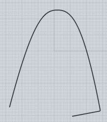
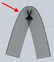
In the case of that one surface, I noticed some strange shading glitches near the bottom which is often a strong clue that there might be a problem with the surface in that area. Examining the control points for a surface can help to see if there is a problem with the way they are organized, they normally shouldn't have a kind of chaotic arrangement for the surface to work well.


> What is Network?

Network is another command to create surfaces, kind of in a similar way to sweep except the mechanism for it is a little different. But it does work by using a grid of curves that cross each other kind of similar to the way you would have sweep rails (and scaling rail) and sweep profiles that cross each other.

It builds the surface more in a "direct" sense, more similar to lofting. Instead sweep works in a way of making the profiles actually travel along the rails.

Check out here for some examples of Network.


> All these problem areas effecting fillet – are they going to
> effect other manipulations of the surface such of Booleans, sweeps?

Yes, for some of these operations.

The tightly curved area should not be a problem for booleans, but it will have a strong effect on Shell or Offset operations, they need to go a constant distance away in the same way as Fillet. Fillet actually incorporates an offset calculation inside of it.

The kind of messy surface at the tip probably means that the surface is kind of zig-zagging back and forth across itself down in that area, that kind of overlapping "folded on itself" type surface will cause problems for boolean operations.


I haven't had a chance to look at your attachment yet, I will take a look shortly and see if I can give you some comments more specifically on that. But just a quick note - really the Stretch command in AutoCAD is the same thing as turning on curve control points and doing a window select to only select the points inside that area, and then moving those to the side.

For example for things like rectangles and lines you should see the same behavior between AutoCAD Stretch and that above procedure in MoI of Control Points + window select + move.

- Michael

EDITED: 24 Jul 2008 by MICHAEL GIBSON

  Reply Reply More Options
Post Options
Reply as PM Reply as PM
Print Print
Mark as unread Mark as unread
Relationship Relationship
IP Logged

Previous
Next
 From:  Michael Gibson
1807.11 In reply to 1807.8 
Hi Olga,

> The only way I see is to explode/trim the rail then I have
> a snap but I am loosing smoothness of the bottom part.

This would be the most normal way to force it to go exactly through the point you want, because by trimming the piece it forces you to get control points positioned exactly at the ends of the pieces.

You can maintain smoothness if you drag all the surrounding control points together at the same time instead of only the single ending ones.

You don't actually need to explode first before trimming, go like this:

Go to the right-side view and select this curve:


Run Edit/Trim, at the "Select cutting objects" prompt select the vertical curve as the cutting object, then Right-click in the viewport to finish picking cutting objects (or push the "Done" button, right-click is a shortcut for that), then at the "Select pieces to remove" prompt, right-click again to keep all pieces instead of discarding any.

That will split the curve into 2 pieces, here is just one of them selected:


Select both pieces and turn on control points by Edit/Show pts. Now select all 3 of the points along the bottom:


And click on the middle one and drag downward, and you will get an "int" snap (there is also a quad very nearby which is ok to grab as well) where the vertical line intersects the lower shape to get a good alignment:


The key thing for curve smoothness is that the 2nd point to the inside of a curve is important along with the ending point.

Those 2 points together define the tangent direction of the curve so if you move them together the tangent direction will not be disturbed.


There is actually another way to drag a point located on the curve to a different location - that is done by turning on control points for a curve, and then clicking and dragging on a point on that same curve. That will grab the point that you clicked on and move it to a new location and reposition the control points so that the curve goes through the new spot. But that tool does not work very well here because the "source point" is just the closest point to the curve from your mouse and is not snapped on to this specific "bottom most" point that you need in this case.

- Michael

  Reply Reply More Options
Post Options
Reply as PM Reply as PM
Print Print
Mark as unread Mark as unread
Relationship Relationship
IP Logged

Previous
Next
 From:  malvin
1807.12 In reply to 1807.9 
Hi Burr
Thank you very much for your help.
-Thanks - Olga-
  Reply Reply More Options
Post Options
Reply as PM Reply as PM
Print Print
Mark as unread Mark as unread
Relationship Relationship
IP Logged

Previous
 From:  malvin
1807.13 In reply to 1807.11 
Hi Michael

Thank you very much for the detailed explanations.
Thank for the advice "AutoCAD Stretch and that above procedure in MoI of Control Points + window select + move"

I did not know MOI could do this so it solves the issue. Now I know how to stretch in MOI.

A lot of useful information.

-Thanks - Olga-
  Reply Reply More Options
Post Options
Reply as PM Reply as PM
Print Print
Mark as unread Mark as unread
Relationship Relationship
IP Logged
 

Reply to All Reply to All