FAQ
Frequently Asked Questions ![]() (French version here)
(French version here)
Contents
- 1 Q: How do I install a plug-in script?
- 2 Q: What about a Mac or Linux version?
- 3 Q: Why can I export to .obj format, but cannot read .obj format into MoI?
- 4 Q: Why does show points work for some objects but not others?
- 5 Q: Why do I get small shading errors when exporting to some rendering programs?
Q: How do I install a plug-in script?
MoI plug-in scripts usually come as a .zip file, where the .zip file contains 2 files, an .htm file and a .js file. To install the plug-in you need to unzip it and then copy those 2 files into MoI's commands folder.
Starting with MoI v4, MoI will now look for commands in 2 places, the commands folder inside the MoI application and also in the appdata Moi commands folder. It is recommended to copy plugins to the appdata folder so that new versions of MoI that you install will find them without needing any additional copying.
On Windows you can find the Moi appdata folder by typing Win+R to bring up the Windows "Run" dialog and then type in:
%AppData%\Moi\commands
On Mac from a Finder window, go to the menu and pick Go > "Go to folder" and type in:
~/Library/Application Support/Moi/commands
Once the files are copied into the commands folder that will make a new command available to MoI. To trigger the new command set up a shortcut key and put in the new command name in the "command" part of the shortcut key.
The command name is the base name of the files that you copied, so if a plug-in has files name ExamplePlugin.htm and ExamplePlugin.js, when you copy those into the commands folder it will make a command named ExamplePlugin available, so when you set up the shortcut key put in: ExamplePlugin as the command name.
Note that the .htm and .js files should be directly contained inside MoI's commands folder and not nested down in any sub-folder beneath commands. Also for the command to run your shortcut key should contain just the plain command name as described above, no file extension and no script: prefix at the front.
Q: What about a Mac or Linux version?
A Mac version has just been released, announcement here.
Right now a Linux specific version is not planned, but the current v3 Windows version beta will run under Linux using Wine as long as you have good enough video drivers. Getting quality 3D accelerated video drivers seems to be a significant issue on Linux currently though.
Q: Why can I export to .obj format, but cannot read .obj format into MoI?
MoI is focused on modeling using NURBS objects, which are made up of smooth curves and surface patches. It's a significantly different way of structuring an object than a polygon mesh method, which is the kind of data that is contained in .obj, .3ds, .stl and .lwo files.
When you export from MoI to one of these polygon mesh formats, MoI will dice up its smooth surfaces into smaller polygon facets to create a polygon mesh. But it is not easy to go the reverse direction and take diced up polygons and create larger smooth surfaces back from them. It's kind of like how you can take a bunch of apples and smash them into applesauce, but it is hard to start with applesauce and go back to apples.
If you want to use a polygon mesh object as a kind of reference object to snap on to while drawing something new in MoI, check out this tool: Obj23dmWireframe converter which will allow you to convert all the edges of a polygon mesh .obj file into a line segments in a .3dm file which can then be loaded into MoI. That enables you to basically use the wireframe of the mesh in MoI as a guide.
Q: Why does show points work for some objects but not others?
MoI won't let you turn on points if you have an object made up of joined surfaces, where the surfaces do not have aligned control points along their common edges. This can happen easily when surfaces are intersected such as in the Boolean commands.
The points are not shown in that situation because it would be too easy to drag the points and cause a gap to open up along what should be a shared sealed edge.
You can get the points to turn on by using Edit/Separate to break your joined object into individual separate surfaces. You can always show points for an individual surface because it does not have this "pull apart shared edge" issue, since it doesn't have edges shared with other surfaces anymore.
Here are some pictures to explain it further.
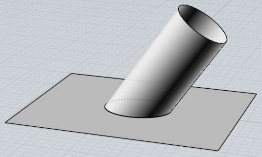
Here is a plane and a cylinder that I have intersected and trimmed with one another:

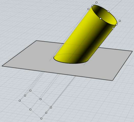
Here are the control points for the cylinder surface:

Note how there are no control points along the intersection edge with the plane - that edge is what is called a "trim curve", it is a curve that has been calculated that exists on the surface, but it is not directly connected to the control point structure of the surface. So you can't modify the surface by pulling on the trim curve itself, the trim curve has its own control points that are separate from the surface's control points.
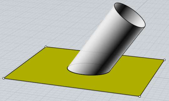
Here are the points for the plane, just 4 points at the corners:

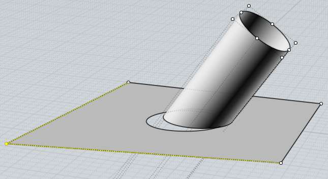
So you can see here that the 4 points for the plane do not match up in any way to the control points for the cylinder. here is what happens now if I grab one of the points of the plane and drag it, it opens up a gap:

This is kind of a fundamental thing for how NURBS modeling works, it has to do with the creation of those "trim curves" that live on a surface but are separate from the surface's control points.
After you have surfaces connected to each other by trim curves like these, you can't easily make modifications by moving surface control points around and still have the connections between the trim curves stay intact.
So the whole trim curve system does not really lend itself to point squishing - however it is also the key thing that makes Boolean operations work really well with NURBS models, since as you do multiple Boolean operations the surfaces themselves don't change, just new trim curves are calculated. With a polygon type modeler, each boolean operation actually dices the polygon surfaces themselves up into a whole lot of small pieces. But since polygon modelers do not have trim curves, they stay a lot more squishable by point manipulation.
Q: Why do I get small shading errors when exporting to some rendering programs?
That usually means that your rendering program is not reading in the smoothing information and is trying to calculate smooth shading by just averaging the normals between adjacent polygons. That kind of automatically calculated smoothing can easily lead to glitches especially in areas where there are polygons of different sizes next to one another.
If you can instead get accurate shading normals into your program, it will avoid these kinds of glitches and help get super smooth looking renderings.
To get accurate normals, first you need to use a file format that supports vertex normals. Usually .obj format is the best choice, except use .lwo for Modo and for Blender use .lwo along with this Blender import script. Avoid using file formats that don't support normals such as .stl and .3ds.
Sometimes when importing an .obj file into your application, there will be some checkbox options for "use normals", or "load vertex normals", etc... - make sure that is enabled.
Also some programs cannot deal with welded meshes in the .obj file, so turning welding off can help in some cases. For example turning welding off makes normals come through ok to Electric Image. To turn welding off, during the mesh export click the little arrow in the lower-left corner of the "Meshing options" dialog box to expand it to detailed settings, and uncheck "Weld vertices along edges".