Fanlight frame chamfers are detached.

Next
 From:  nycL45
2765.1 
I was doing a final review and found *most* of the fanlight frame chamfers had become detached and the core mixed with and without chamfers. Another attempt resulted in the core mostly gone. AFAIK, I did not touch any controls that would partially separate the chamfers.

What I did:

The original splines seem to be closed although two segments required additional work.

The half circle was first extruded and then the segments were then booled from the half circle solid. The chamfer tool, with square corners checked, was then used. The middle fanlight frame, in the group pic below, was chamfered on side at a time. With the other fanlight, to the right, all edges on both sides were selected and then chamfered at one time.

Need some help on this.

The file contains the splines and solids.

Thanks,

Leonard

  Reply Reply More Options
Post Options
Reply as PM Reply as PM
Print Print
Mark as unread Mark as unread
Relationship Relationship
IP Logged

Previous
Next
 From:  BurrMan
2765.2 In reply to 2765.1 
That happens to fillet/chamfer tool when a value that doesnt really fit for the operation is used. I went up to .2 ok, anything larger produces the funky results.

I've also found that if I need to squeeze up the size towards that limit, I can quit the command and start it again and get slightly higher results. So like for this when I created the bad chamfer with a large value, then tried to go smaller, bigger, smaller to find the limit, it stopped me at .2. When I closed the command and reselected the geometry, and then started it again and just entered .24, it chamfered well. You could also try smaller sections at a time to get larger results. Like one opening at a time.

FYI.
  Reply Reply More Options
Post Options
Reply as PM Reply as PM
Print Print
Mark as unread Mark as unread
Relationship Relationship
IP Logged

Previous
Next
 From:  Michael Gibson
2765.3 In reply to 2765.1 
Hi Leonard, it looks like there may have been a failure to trim some of the pieces when the chamfer was done. When that happens the chamfer pieces are still generated so that you have something to work with.

I'm taking a look at your model, but one quick initial note for you, you wrote:

> The half circle was first extruded and then the segments were
> then booled from the half circle solid.

You can actually extrude this all at once instead of extruding only the outer region and then doing booleans.

If you are extruding a set of curves all in the same plane, Extrude knows how to look for nested internal regions and form holes out those.

So for example, just take your entire set of curves and extrude it like this:


- Michael
Attachments:

  Reply Reply More Options
Post Options
Reply as PM Reply as PM
Print Print
Mark as unread Mark as unread
Relationship Relationship
IP Logged

Previous
Next
 From:  nycL45
2765.4 
Thanks BurrMan and Michael.

I found the same issue occurs with the Fillet tool. I will reduce the face and radius dims.

That is good to know, Michael. I will put that to work right away.

Cheers,

Leonard

I just tried your tip Michael. Very nice.

Another question. Is there a faster way to track down and correct points that do not align for joining?

L.

EDITED: 11 Jul 2009 by NYCL45

  Reply Reply More Options
Post Options
Reply as PM Reply as PM
Print Print
Mark as unread Mark as unread
Relationship Relationship
IP Logged

Previous
Next
 From:  BurrMan
2765.5 In reply to 2765.3 
I actually like this! In an older version of MoI, it would just fail. Anytime a fillet would get too close to another edge or something. Now you can put "Huge" values to get a result and then do trimming to produce something like "Filleting past edges". (Michael making NLib as powerful as ParaSolids!) :O
  Reply Reply More Options
Post Options
Reply as PM Reply as PM
Print Print
Mark as unread Mark as unread
Relationship Relationship
IP Logged

Previous
Next
 From:  Michael Gibson
2765.6 In reply to 2765.4 
Hi Leonard, also one other note - when selecting edges to chamfer, it can sometimes be easiest to select the ones that you don't want, and then use Select / Invert (which is good to put on a keyboard shortcut for something like the I key, for the command you put in: script:moi.geometryDatabase.invertSelection(); )

So for example in this case where you don't want to chamfer the outer edges which are fewer in number than the inside ones, select the outer edges, then push I, or there is a button for it on the Select palette on the side pane.


> Is there a faster way to track down and correct points that do not align for joining?

If you see that there is a problem, you might undo and then try joining things just 2 at a time, then when if a pair fails you can know to zoom in on where they are supposed to touch.

I might be able to give you a better tip if I can see an example of where you were running into a problem.

- Michael
  Reply Reply More Options
Post Options
Reply as PM Reply as PM
Print Print
Mark as unread Mark as unread
Relationship Relationship
IP Logged

Previous
Next
 From:  Michael Gibson
2765.7 In reply to 2765.4 
Hi Leonard,

> I found the same issue occurs with the Fillet tool. I will reduce the
> face and radius dims.

Over here, Fillet seems to work with Radius 0.25 with "Straight corners" set to OFF.


But not with straight corners on.

But maybe this is also one of these situations where you can't have straight corners on without causing a problem where pieces just don't match up. Check out a description of the problem here:
http://moi3d.com/1.0/docs/moi_command_reference7.htm#fillet

- Michael
Attachments:

  Reply Reply More Options
Post Options
Reply as PM Reply as PM
Print Print
Mark as unread Mark as unread
Relationship Relationship
IP Logged

Previous
Next
 From:  nycL45
2765.8 
Michael, the invert tip is a good one. I tried to figure out how to do that earlier.

I am getting a strange extrude when I group the curves + extrude; edges are missing in a couple of places. See the pic. You should be able to use the curves enclosed earlier to try duplicating this condition. Orient the axis as indicated in the LL corner. I rebooted Moi and Windows and then recreated the extrude and the results were the same.

L.

  Reply Reply More Options
Post Options
Reply as PM Reply as PM
Print Print
Mark as unread Mark as unread
Relationship Relationship
IP Logged

Previous
Next
 From:  Michael Gibson
2765.9 In reply to 2765.8 
Hi Leonard, that's odd - I can't seem to repeat that last "edges not showing up" problem over here...

Over here when I open up your previous file (Clerestory chamfer problem.3dm) and select all the curves on the left, and then extrude, I get this:


which seems to have all edges in place.

In your screenshot, there must be an edge there since it has the proper shape in that spot.

Have you possibly hidden some of the edges? It is possible to hide edges the same as you can hide regular objects - if you have some edges selected and then push Edit/Hide, they will get hidden from view.

Please try pushing Edit/Hide with nothing selected to show everything and see if that brings your edges back again.

The original problem definitely seems to be a bug where Chamfer is not trimming things properly though, there is plenty of space for your chamfers to fit.

- Michael
Attachments:

  Reply Reply More Options
Post Options
Reply as PM Reply as PM
Print Print
Mark as unread Mark as unread
Relationship Relationship
IP Logged

Previous
Next
 From:  Michael Gibson
2765.10 In reply to 2765.9 
Hi Leonard, I also think I'm understanding a bit more about how you want to use "straight corners" in this case.

So to use straight corners, the little side connecting edges will need to be unselected.

These ones I mean:


Because if those are selected, chamfer or fillet will try to build a surface there and then you can't have straight corners enabled because of this kind of situation:


When a side piece is getting filleted/chamfered, then "straight corners" won't really work anymore because as you can see above the fillets/chamfers do not all intersect with one another and there would be a hole.

So instead you want to avoid selecting those little edges.

In this case you would not want to use Invert (that can come in handy in other situations though), but instead use a strategic window selection to grab things.

To do that, you select just one edge to start with. Once a single edge is selected, then a window select will grab other edges inside of it. So in this case after selecting one edge you would go to the top view, and do 2 window selects like this (note starting on the left and moving towards the right):


Then switch back to the 3D view and deselect the outermost edges that you don't want to have chamfered by clicking on them individually to deselect them.


- Michael

  Reply Reply More Options
Post Options
Reply as PM Reply as PM
Print Print
Mark as unread Mark as unread
Relationship Relationship
IP Logged

Previous
Next
 From:  Michael Gibson
2765.11 In reply to 2765.1 
Hi Leonard, until I figure out what is going wrong with chamfer in this case, probably the best way to complete this would be to use a combination of Offset + Loft instead.

To do that, you go through those current curves you have an offset them to the inside by your chamfer distance, like 0.25 inches I think you were using.

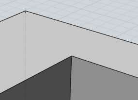
So that gives you this:


Then you move one set of the curves backwards by 0.25 units, so that they are staggered from one another like this:


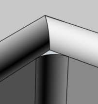
Then you go through and select matching pairs of curves, and run construct / Loft (with cap ends option off) to build the chamfer pieces like this:


After those are all built, switch to the Top view and do a window select to grab all the curves for the front part, like this:


Then run Construct / Planar to build a planar cap surface through those.

At this point the front piece and the chamfers are all built, you can join those together.

Then mirror it to make the back part, (this much is in the attached 3DM file) and then to complete it you'll need to select pairs of edges and use Loft to build the side wall pieces which then can all be joined together.

This should at least allow you to finish the model with your originally desired sizes.

I'm not sure yet why Chamfer is having so many problems with this situation, I'll see if I can figure anything out about that but that may take a few days or so before I know any more about that.

- Michael

  Reply Reply More Options
Post Options
Reply as PM Reply as PM
Print Print
Mark as unread Mark as unread
Relationship Relationship
IP Logged

Previous
Next
 From:  nycL45
2765.12 
Hi Michael,

Let me address some of your responses.

After four straight attempts, I am still getting edges I cannot highlight. I did what you suggested but no joy. I have enclosed a pic of the extrude with the edges I could click on highlighted. The rest of the edges in that pic would not activate. I have attached the file of this latest iteration. The workaround I used was to go back to extrude as I noted here some posts ago. Pics 17 & 18 show the chamfers after the .obj files were dropped into Cinema 4D.

Regarding the "little side connecting edges", I did not include those for the chamfer.

Thanks for the strategic window tip. Good one that will be used frequently.

Regarding the chamfers, I followed BurrMan's suggesting of backing off from .25. The best I could do was .17 and decided to leave it at that. Interestingly, the door rectangular openings accepted the .25 and straight corners just fine.

Thanks for your help.

Leonard

EDITED: 11 Jul 2009 by NYCL45


Image Attachments:
Size: 139.2 KB, Downloaded: 13 times, Dimensions: 1418x974px
Size: 77.6 KB, Downloaded: 14 times, Dimensions: 815x738px
Size: 83.7 KB, Downloaded: 10 times, Dimensions: 875x636px
  Reply Reply More Options
Post Options
Reply as PM Reply as PM
Print Print
Mark as unread Mark as unread
Relationship Relationship
IP Logged

Previous
Next
 From:  Michael Gibson
2765.13 In reply to 2765.12 
Hi Leonard, thanks for attaching that file "Clerestory edge problem.3dm".

When I load that file I can definitely see that you have some edges not displayed there.

But they do seem to exist and are just hidden. If I click the Edit/Hide button located in the UI here:


immediately after loading your file, the edges are unhidden and then can be seen and picked.

What happens if you follow these exact steps:

1 - load your just attached file Clerestory edge problem.3dm

2 - push that hide button

Do you then see the edges?

- Michael
Attachments:

  Reply Reply More Options
Post Options
Reply as PM Reply as PM
Print Print
Mark as unread Mark as unread
Relationship Relationship
IP Logged

Previous
Next
 From:  Michael Gibson
2765.14 In reply to 2765.12 
Hi Leonard, also I've been examining the chamfer problem some more - it seems to be a general bug in how chamfer handles the "corner patching" pieces when 2 edges meet each other at an angle of less than 90 degrees like when you have a triangular shaped hole.

I've been able to repeat the problem when making a simple triangular hole in other simple models separate from yours.

I may need to send it in to the people who make the geometry library that I use, but identifying a general pattern to the problem can help to isolate it down.

- Michael
  Reply Reply More Options
Post Options
Reply as PM Reply as PM
Print Print
Mark as unread Mark as unread
Relationship Relationship
IP Logged

Previous
Next
 From:  Michael Gibson
2765.15 In reply to 2765.12 
Hi Leonard,

> Interestingly, the door rectangular openings accepted the .25
> and straight corners just fine.

Yeah, it seems that edges that meet at 90 degrees or higher are handled fine, it's the ones sharper than that from triangular holes that are not handled properly.

Let me know if you would like me to cook up a version with the .25 value, using that alternate method Offset + Loft method. I can complete that partially finished version that I posted earlier if you want.

- Michael
  Reply Reply More Options
Post Options
Reply as PM Reply as PM
Print Print
Mark as unread Mark as unread
Relationship Relationship
IP Logged

Previous
Next
 From:  nycL45
2765.16 
Hi Michael,

Yes the Edit/Hide button reveals the edges but I think that it is actually turning on and using the original or generating curve and not using just the solid's edges. This is what I did using the file I sent you:
1. Assign the solid an Object name. I used "Solid".
2. Turn off Object "Solid".
3. Turn on Object "Spline clerestory all crvs".
a. You can see there are strange curve remnants along with the original generating curve (pic below).
b. Click on the outer most semi-circular curve (or pie shaped) and then note that the window in the upper right corner indicates that what has been activated is a solid, not a curve.
c. Under the Object list, the "Spline..." has a full eye and "Solid" has half an eye. Doesn't that mean that "Solid" is partially on? I noticed that the half eye occurs a lot when extrude has been used.
1) clicking the half eye turns on "Solid".
2) "Spline..." should still have a full eye.
3) turn off "Spline..."
4) the solid that is left has numerous edges that cannot be activated.

I thought that once the extrusion was created, the generating spline was redundant and could be deleted. I have done that without causing problems.

Leonard
Image Attachments:
Size: 89.4 KB, Downloaded: 13 times, Dimensions: 1000x625px
  Reply Reply More Options
Post Options
Reply as PM Reply as PM
Print Print
Mark as unread Mark as unread
Relationship Relationship
IP Logged

Previous
Next
 From:  nycL45
2765.17 
>Let me know if you would like me to cook up a version with the .25 value, using that alternate method Offset + Loft >method. I can complete that partially finished version that I posted earlier if you want.

Michael,

Thanks for the offer but that is not necessary at this time. If I need it, I will complete yours.

Leonard
  Reply Reply More Options
Post Options
Reply as PM Reply as PM
Print Print
Mark as unread Mark as unread
Relationship Relationship
IP Logged

Previous
Next
 From:  Michael Gibson
2765.18 In reply to 2765.16 
Hi Leonard, thanks for posting more details on your edge hiding problem.

What you're running into there is a bug where the name property of the original generating curve is actually being transmitted to some but not all of the edge curves of the resulting solid.

So once they have the same name, they all get turned on or off when using that same slot in the "Objects" section of the scene browser.

I'll get this fixed up for the next beta so that those edges will not inherit the name of the generating curve, that's kind of a bad side effect from a mechanism that tries to maintain object properties whenever an object is copied - in this case some edge curves in the resulting solid come from direct copies of the original input curve.

- Michael
  Reply Reply More Options
Post Options
Reply as PM Reply as PM
Print Print
Mark as unread Mark as unread
Relationship Relationship
IP Logged

Previous
 From:  nycL45
2765.19 
Michael,

Thanks for the explanations, tips and help.

Cheers,

Leonard
  Reply Reply More Options
Post Options
Reply as PM Reply as PM
Print Print
Mark as unread Mark as unread
Relationship Relationship
IP Logged
 

Reply to All Reply to All