Considering buying MOI to do this
 1-15  16-35  36-55  56-69

Previous
Next
 From:  Barry-H
8732.16 In reply to 8732.15 
Hi Bruno,
try this.
Barry


Attachments:

  Reply Reply More Options
Post Options
Reply as PM Reply as PM
Print Print
Mark as unread Mark as unread
Relationship Relationship
IP Logged

Previous
Next
 From:  Bruno (ZOOROPA)
8732.17 In reply to 8732.16 
Thanks @Barry-H .

Getting there. Tomorrow I will continue.
Image Attachments:
Size: 578.3 KB, Downloaded: 16 times, Dimensions: 1926x1610px
  Reply Reply More Options
Post Options
Reply as PM Reply as PM
Print Print
Mark as unread Mark as unread
Relationship Relationship
IP Logged

Previous
Next
 From:  Michael Gibson
8732.18 In reply to 8732.8 
Hi Bruno,

re:
> Is it possible to blend curves in Moi ? ?

Yup, select your curves and then run the Construct > Blend command.

One of the differences between MoI and Rhino is that MoI doesn't have separate commands for doing things to curves and surfaces, there's just one Blend command and it will do either a curve blend or a surface blend depending on what you have selected.

- Michael
  Reply Reply More Options
Post Options
Reply as PM Reply as PM
Print Print
Mark as unread Mark as unread
Relationship Relationship
IP Logged

Previous
Next
 From:  Michael Gibson
8732.19 In reply to 8732.15 
Hi Bruno,

re:
> Questions: Is there any way to project the lines faster? Maybe a contour ? Maybe an offset of each oblique line ?

I'd probably make one line and then use Transform > Array > Dir to duplicate it to make the rest of them.

- Michael
  Reply Reply More Options
Post Options
Reply as PM Reply as PM
Print Print
Mark as unread Mark as unread
Relationship Relationship
IP Logged

Previous
Next
 From:  Bruno (ZOOROPA)
8732.20 In reply to 8732.18 
Thanks Michael. I also noticed that the blend has less options than Rhino. For example the ends of the blend are managed always under the same continuity.

Is this right ?

Thanks
  Reply Reply More Options
Post Options
Reply as PM Reply as PM
Print Print
Mark as unread Mark as unread
Relationship Relationship
IP Logged

Previous
Next
 From:  Bruno (ZOOROPA)
8732.21 In reply to 8732.19 
That was the technique! Thanks!
  Reply Reply More Options
Post Options
Reply as PM Reply as PM
Print Print
Mark as unread Mark as unread
Relationship Relationship
IP Logged

Previous
Next
 From:  Bruno (ZOOROPA)
8732.22 
I tried making one surface with Rhino imported curves and other one natively in MOI.

I must say the result is the same. Please not misunderstand. The sweep was always performed by MOI which looks neater.

I am just thinking that I could import all my lines from Rhino. I just wanted to check if this is as expected to happen. As long as the procedure is performed by Moi the structure in Rhino will not change the behavior in respect to the one made in Moi.


Thanks a lot.

You can check here.

Red one is coming from Rhino. Grey Moi. In order to see the isocurves I imported to Rhino again both.
  Reply Reply More Options
Post Options
Reply as PM Reply as PM
Print Print
Mark as unread Mark as unread
Relationship Relationship
IP Logged

Previous
Next
 From:  Michael Gibson
8732.23 In reply to 8732.20 
Hi Bruno,

> Thanks Michael. I also noticed that the blend has less options than Rhino. For example the ends of the blend are managed always under the same continuity.
>
> Is this right ?

Yes, that's correct. If you need a really fancy blend with different continuity for each individual end I'd recommend doing it in Rhino and then bring it back into MoI. You can use copy/paste Ctrl+C/Ctrl+V to move objects back and forth between MoI and Rhino quickly.

- Michael
  Reply Reply More Options
Post Options
Reply as PM Reply as PM
Print Print
Mark as unread Mark as unread
Relationship Relationship
IP Logged

Previous
Next
 From:  Michael Gibson
8732.24 In reply to 8732.22 
Hi Bruno,

> I am just thinking that I could import all my lines from Rhino. I just wanted to check if this is as
> expected to happen. As long as the procedure is performed by Moi the structure in Rhino will not
> change the behavior in respect to the one made in Moi.

Sorry I'm not quite following this part, what is the question exactly?


> Thanks a lot.
>
> You can check here.
>
> Red one is coming from Rhino. Grey Moi. In order to see the isocurves I imported to Rhino again both.

Did you mean to attach something to your post? I didn't see anything. Also it really does help if you can post a 3DM model file that can be loaded and zoomed and rotated around and inspected in detail rather than only an image, you can e-mail them to me at moi@moi3d.com if you want, if you sent one previously please re-send it as I don't seem to have received any.

- Michael
  Reply Reply More Options
Post Options
Reply as PM Reply as PM
Print Print
Mark as unread Mark as unread
Relationship Relationship
IP Logged

Previous
Next
 From:  Bruno (ZOOROPA)
8732.25 In reply to 8732.24 
Hi Michael! Yes I forgot ...Just uploaded now.

I mean the result between making the model in Moi and importing the lines from Rhino and making the sweep in Moi...seems to be the same.

I guess I can import all my lines from rhino and do the sweep in MOI.
Attachments:

  Reply Reply More Options
Post Options
Reply as PM Reply as PM
Print Print
Mark as unread Mark as unread
Relationship Relationship
IP Logged

Previous
Next
 From:  Michael Gibson
8732.26 In reply to 8732.25 
Hi Bruno,

> I mean the result between making the model in Moi and importing the lines from Rhino
> and making the sweep in Moi...seems to be the same.

Yes, that does make sense for the case of using Sweep - Sweep does not use the control point structure of the rail curves directly, a sweep is formed by an iterative refinement process which means it's only really the shape of the curves that is important not particularly how many control points are in it.

It looks like the problematic part of your sweep is a bend where the radius of the bend is tighter than the width of the curve going around it, that tends to produce a bunching effect similar to this:


- Michael
  Reply Reply More Options
Post Options
Reply as PM Reply as PM
Print Print
Mark as unread Mark as unread
Relationship Relationship
IP Logged

Previous
Next
 From:  Michael Gibson
8732.27 In reply to 8732.25 
Hi Bruno, another thing you might try is to use the long curves as the profiles for the sweep and the short curves for the rails. The reason to try that is that it can be easier to control how the profiles connect to each other by their segment structure. For example here I've rebuilt the corner areas to make them single segments structured like this:


Then if joined together and used as profile curves for the sweep, it will result in those areas being matched with each other and that will probably help get a better shape in those tighter bend areas:


If you look at the surface control points generated from this method in those corners, it looks like this:


That looks pretty good, with things more evenly spread from one station to the next, the things that cause poor quality surfaces are when the stations are kind of diagonally slanting or crossing over each other because of bunching.

- Michael

  Reply Reply More Options
Post Options
Reply as PM Reply as PM
Print Print
Mark as unread Mark as unread
Relationship Relationship
IP Logged

Previous
Next
 From:  mkdm
8732.28 In reply to 8732.27 
Hi Michael!

...reading your last post looks like Moi has a new display routine....a new and smoother mesh shader.

Is that the case or not ?

If I remember well some times ago you talked about new improvements for the display engine of V4.

Thanks! (I will read you reply tomorrow morning)

- Marco (mkdm)
  Reply Reply More Options
Post Options
Reply as PM Reply as PM
Print Print
Mark as unread Mark as unread
Relationship Relationship
IP Logged

Previous
Next
 From:  Michael Gibson
8732.29 In reply to 8732.28 
Hi Marco,

> ...reading your last post looks like Moi has a new display routine....a new and smoother mesh shader.

I'm glad that you like it! That's actually a screenshot of V3, it's just the standard MoI display engine that looks like that.

If you open that file you should see the same thing over there, if you want the exact same shading go to Options > View > "Lighting options" and set it like this:


- Michael
Attachments:

  Reply Reply More Options
Post Options
Reply as PM Reply as PM
Print Print
Mark as unread Mark as unread
Relationship Relationship
IP Logged

Previous
Next
 From:  Bruno (ZOOROPA)
8732.30 In reply to 8732.26 
Hi Michael,

In Rhino I started to re-construct the model by changing the degrees and control point of the curves (each segment). I managed to make a lot of single span surface.
That is the reason I thought the rials structure do interfiere with the sweep action.

Another doubt that I have is why the outcome of the intersection between my rounded cube and my lines projected, meaning the ''triangles'' that I am using as rials have so many control points on the curved segments. Rhino also gave me these curves with a LOT of control points.

I re-built them and then the sweep was much more cleaner. That Is the reason why I am confused by the ''- Sweep does not use the control point structure of the rail curves directly"

Thanks so much for your dedication
  Reply Reply More Options
Post Options
Reply as PM Reply as PM
Print Print
Mark as unread Mark as unread
Relationship Relationship
IP Logged

Previous
Next
 From:  Bruno (ZOOROPA)
8732.31 In reply to 8732.27 
Hi Michael. I wanted to ask you a few things regarding to the new proposed technique.

1. How did you find the rial curves for the segments (attachment)

2. Is there any reason why you connect one of the 'radius' of the curve to the perpendicular part of the other one and not with the 'radius' of the other one ?


Thanks a lot!
Image Attachments:
Size: 29 KB, Downloaded: 5 times, Dimensions: 667x561px
  Reply Reply More Options
Post Options
Reply as PM Reply as PM
Print Print
Mark as unread Mark as unread
Relationship Relationship
IP Logged

Previous
Next
 From:  Michael Gibson
8732.32 In reply to 8732.30 
Hi Bruno,

re:
> I re-built them and then the sweep was much more cleaner. That Is the reason why I am
> confused by the ''- Sweep does not use the control point structure of the rail curves directly"

Maybe the dense curves also had some slight oscillations which can be difficult to see, and the rebuilt ones are smoother.

Or it could also be a matter of what's called "parameterization" of the curve, which has to do with how evaluating the curve might have spots where marching along the curve in the curve's parameter space may be either stretched out or compressed together instead of producing evenly spaced points.

Anyway, just to demonstrate it try sweeping the 2 cases in the attached file and then look at the control points of the rails.

Dense control points do give more potential for a curve to possibly have little tiny wiggles in it though so it can be good to be suspicious of them but it's not necessarily automatically bad.

- Michael

  Reply Reply More Options
Post Options
Reply as PM Reply as PM
Print Print
Mark as unread Mark as unread
Relationship Relationship
IP Logged

Previous
Next
 From:  mkdm
8732.33 In reply to 8732.29 
Hello Michael.

Ah...ok...

No new things but anyway thanks a lot for this lighting options!

Yes...I already new that kind of things since the old days of the original "Majik Primer: MoI's Lighting Options and You!" forum thread :)
(at http://moi3d.com/forum/index.php?webtag=MOI&msg=5222.45)

One of my favorite plugins that I use daily.

Thanks. Have a nice day.

- Marco (mkdm)
  Reply Reply More Options
Post Options
Reply as PM Reply as PM
Print Print
Mark as unread Mark as unread
Relationship Relationship
IP Logged

Previous
Next
 From:  Michael Gibson
8732.34 In reply to 8732.31 
Hi Bruno,

> 1. How did you find the rial curves for the segments (attachment)

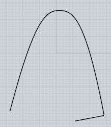
To set it up I drew in a line across using "Perp" snap like this:


Then I used that line to trim the profiles and used Rebuild (http://moi3d.com/3.0/docs/moi_command_reference10.htm#rebuild) to make those into single segment curves instead of being made up of 3 segments.


> 2. Is there any reason why you connect one of the 'radius' of the curve to the
> perpendicular part of the other one and not with the 'radius' of the other one ?

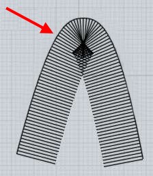
It's to give a more gradual transition to the straight parts. If you match radius to radius it will make for a very sudden transition in a stretched out zone here:


If you turn on control points for that you can see the straight segments have stations that are slanting and stretching a lot, especially with elongating into a kind of sharp spike at the tip:


That type of slanting will usually have some undesirable effect on the surface's shape in those areas, it just becomes more difficult to control the shape.

If you match it the other way and then look at the same section you can see a much more orderly arrangement of stations, the more that they resemble regular planar formations it tends to give more controlled surface shaping there as well.


This kind of thing comes into play when you're trying to connect together outlines that have zones of different length from each other. Just matching things by "small feature to small feature directly" can produce shearing and so can just an overall "match full length to other full length".

- Michael

  Reply Reply More Options
Post Options
Reply as PM Reply as PM
Print Print
Mark as unread Mark as unread
Relationship Relationship
IP Logged

Previous
Next
 From:  Karsten (KMRQUS)
8732.35 In reply to 8732.31 
Hello Bruno,

another way to get cleaner surfaces is to use a G2 or G3 blends for the radii of your cube and not a G1 (classical radius). Have a look in the fillet command. The resulting curves of the projection/slices will have also a better continuity. The resulting surfaces don't have seams. Have a look to my first post.

Have a nice day
Karsten
  Reply Reply More Options
Post Options
Reply as PM Reply as PM
Print Print
Mark as unread Mark as unread
Relationship Relationship
IP Logged
 

Reply to All Reply to All


Show messages:  1-15  16-35  36-55  56-69