Looking for someone to modify an existing MoI script in return for beer money (or whatever :)
 1-7  8-21

Previous
Next
 From:  Michael Gibson
8370.8 In reply to 8370.5 
Hi Ed, re:

> Sure Michael - see attached 3DM.

I just took a look at it and I noticed there weren't any object names set in it, were you expecting the script to identify profiles A B and C just by their left to right arrangement as in that file or should they have names assigned to them?

Are profiles always to be specified as planar curves in the Front view, in the X/Z plane?

- Michael
  Reply Reply More Options
Post Options
Reply as PM Reply as PM
Print Print
Mark as unread Mark as unread
Relationship Relationship
IP Logged

Previous
Next
 From:  ed (EDDYF)
8370.9 In reply to 8370.8 
Michael & Brian - Thanks for attempting this script!

1. Sorry, I forgot to name the 3 profiles. They need names assigned - call them anything as long as they can be selected by the menu.

2. Yes - Profiles to be planar curves in the Front view, in the X/Z plane. That way the ring imports into the printer's slicer program in the correct orientation.

3. A ring solid created via Revolve is fine.

4. Using the standard ring diameters from the existing script, the left side of the profile should rest on the circle (rail). In other words, when the ring is printed, the inside diameter should measure the same as the circle diameter that is associated with the selected ring size in the .htm.

5. The ring profile must be scaled in Z only to match the Ring Width selected via the menu. X should remain constant as the ring shank remains a constant thickness, regardless of ring size.

6. As a final step, the ring solid should be scaled larger overall by 5% to compensate for shrinkage when it prints. A single scaling variable would be easier to match to a specific printer/ filament combination, rather than individually adjusting the ring size constants in the .htm.

- Ed
  Reply Reply More Options
Post Options
Reply as PM Reply as PM
Print Print
Mark as unread Mark as unread
Relationship Relationship
IP Logged

Previous
Next
 From:  bemfarmer
8370.10 
The leftmost point of the left side of a profile will correspond to the inner surface of the ring.

After doing a few tests:
Using Bounding Box looks very useful.
Bounding Box center, adjusted by subtracting BB xLength/2 from x coordinate, gives Orient Line Line base line start point.
BB center, adjusted by adding BB zLength/ to z coordinate, gives Orient Line Line base line end point.
The start point of the ring circle, on the + x axis, will be the Orient Line Line target start point.
The start point of the ring circle, with ringWidth/2 added to the z coordinate, will be the Orient Line Line target end point.
Orient to be in the Stretch mode.
(The above math is off the cuff, and might not be perfect.)

Then do revolve.

A concave inner profile seems doubtful ...

The coding seems relatively easy, (which would mean many hours for myself :-)
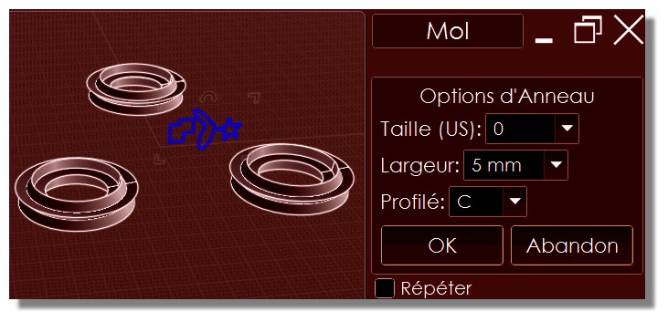
Not sure about how to do .2mm width increments, except with slider...

- Brian
  Reply Reply More Options
Post Options
Reply as PM Reply as PM
Print Print
Mark as unread Mark as unread
Relationship Relationship
IP Logged

Previous
Next
 From:  Michael Gibson
8370.11 In reply to 8370.1 
Hi Ed, one other question - for the STL export part do you want the "Mesh options" dialog with meshing controls to pop up or would you rather it not show and instead some fixed meshing parameters used instead and if so what parameters.

- Michael
  Reply Reply More Options
Post Options
Reply as PM Reply as PM
Print Print
Mark as unread Mark as unread
Relationship Relationship
IP Logged

Previous
Next
 From:  ed (EDDYF)
8370.12 In reply to 8370.11 
Michael -

I'd like to use fixed meshing options and avoid the pop-up.

Because these are small models I use:

More Polygons slider = Maximum

Display: Shaded + edges

Angle = 3

Divide larger than: 1 ALL

Avoid smaller than: Blank
Aspect ratio limit: blank

- Ed
  Reply Reply More Options
Post Options
Reply as PM Reply as PM
Print Print
Mark as unread Mark as unread
Relationship Relationship
IP Logged

Previous
Next
 From:  Michael Gibson
8370.13 In reply to 8370.12 
Hi Ed, please try the attached MakeRing plugin (instructions for installing plug-ins here).

I hope it does what you wanted! If the person using it will not know how to zoom and pan around it may be a good idea to save the template file with the profiles in it with the views set up so that they can easily see the generated rings without needing to zoom around.

- Michael
Attachments:

  Reply Reply More Options
Post Options
Reply as PM Reply as PM
Print Print
Mark as unread Mark as unread
Relationship Relationship
IP Logged

Previous
Next
 From:  bemfarmer
8370.14 In reply to 8370.13 
Cool, elegant and professional!

Note, the 3 profiles need to be named A, B, and C, in the preloaded .3dm file.

- Brian

EDITED: 11 Apr 2017 by BEMFARMER

  Reply Reply More Options
Post Options
Reply as PM Reply as PM
Print Print
Mark as unread Mark as unread
Relationship Relationship
IP Logged

Previous
Next
 From:  Frenchy Pilou (PILOU)
8370.15 
And what is the last ring.3dm or maybe 3 curves (?) to draw and select for run this script ?
  Reply Reply More Options
Post Options
Reply as PM Reply as PM
Print Print
Mark as unread Mark as unread
Relationship Relationship
IP Logged

Previous
Next
 From:  Michael Gibson
8370.16 In reply to 8370.15 
Hi Pilou, to run the script get the 3DM file from here: http://moi3d.com/forum/index.php?webtag=MOI&msg=8370.5 and also set object names on each profile, first one named A, second one named B and third one named C.

- Michael
  Reply Reply More Options
Post Options
Reply as PM Reply as PM
Print Print
Mark as unread Mark as unread
Relationship Relationship
IP Logged

Previous
Next
 From:  Frenchy Pilou (PILOU)
8370.17 In reply to 8370.16 
Ok !
But why solids are losted and just saved as STL ?
It's not possible to keep them on the screen as normal 3dm volumes for make any functions?
It's very frustrating! :)

here C : I have tested with any forms of profiles :)
Error messages when profils are not vertical!

EDITED: 11 Apr 2017 by PILOU

  Reply Reply More Options
Post Options
Reply as PM Reply as PM
Print Print
Mark as unread Mark as unread
Relationship Relationship
IP Logged

Previous
Next
 From:  Michael Gibson
8370.18 In reply to 8370.17 
Hi Pilou,

> But why solids are losted and just saved as STL ?

Because that's what was requested for the plug-in to do, to just generate an STL file. It is to help someone who only wants to generate an STL file and not do any other kinds of modeling.

But if you want it's easy to modify it to keep the objects and not generate an STL file automatically. To do that, edit the MakeRing.js file in a text editor. Near the end of the file are 2 lines that have this:

code:
	SaveSTLFile();
	
	RemoveObjects();


If you delete or comment out these 2 lines then the objects will be kept. Commenting out means to put // at the front of the line like this:

code:
	//SaveSTLFile();
	
	//RemoveObjects();


> here C : I have tested with any forms of profiles :)
> Error messages when profils are not vertical!

Ed specified earlier in this thread that the profiles were to be planar in the Front view, see here: http://moi3d.com/forum/index.php?webtag=MOI&msg=8370.9

So the plug-in is only designed to work with those kinds of profiles, it's normal to get an error if your profiles do not match that requirement.

- Michael
  Reply Reply More Options
Post Options
Reply as PM Reply as PM
Print Print
Mark as unread Mark as unread
Relationship Relationship
IP Logged

Previous
Next
 From:  Frenchy Pilou (PILOU)
8370.19 In reply to 8370.18 
Perfect!
+ Flow function :)
and render with the Free SimLab Composer Light! (maxi 1920 * 1080 )
http://www.simlab-soft.com/3d-products/simlab-composer-freelicensee.php#lite

EDITED: 11 Apr 2017 by PILOU

  Reply Reply More Options
Post Options
Reply as PM Reply as PM
Print Print
Mark as unread Mark as unread
Relationship Relationship
IP Logged

Previous
Next
 From:  Frenchy Pilou (PILOU)
8370.20 

EDITED: 11 Apr 2017 by PILOU

  Reply Reply More Options
Post Options
Reply as PM Reply as PM
Print Print
Mark as unread Mark as unread
Relationship Relationship
IP Logged

Previous
 From:  ed (EDDYF)
8370.21 
Michael - Your script works great! Thank you very much.

I'll make some 3D prints this weekend and get the shrinkage factor dialed in. Photos to follow.

In the meantime I'll send you an email this evening - I'd like to send you a token of appreciation.

- Ed
  Reply Reply More Options
Post Options
Reply as PM Reply as PM
Print Print
Mark as unread Mark as unread
Relationship Relationship
IP Logged
 

Reply to All Reply to All


Show messages:  1-7  8-21