Show messages:
1-12
…
33-52
53-72
73-92
93-112
113-129
From: Frenchy Pilou (PILOU)
Depending if you really want the physical material effect or just at the rendering ?
Only material

or simulated by textures
From: Michael Gibson
Hi Gord,
re:
> If I wanted to add a plate effect, where the thing is covered with plates but some
> standing slightly proud. How could that be done?
Do you maybe have an image showing something similar to give a better idea of what you want?
- Michael
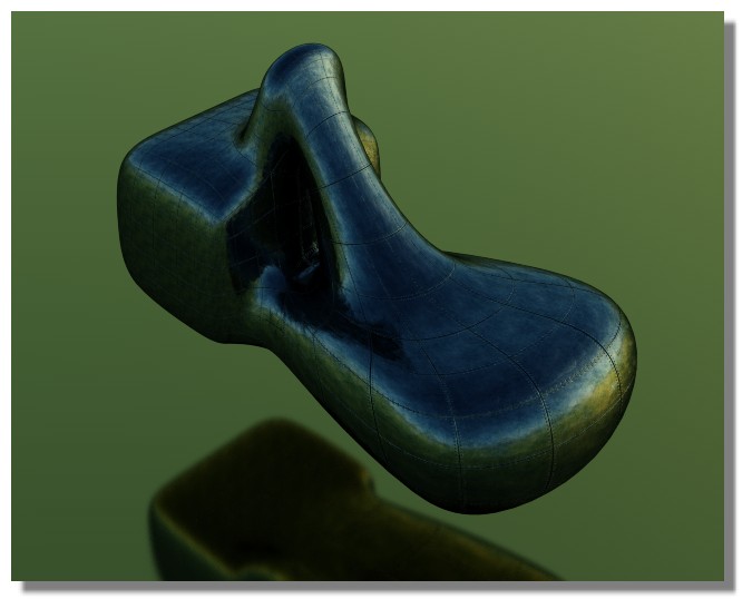
From: Gord (NEOMEGA)
This sort of thing?
Image Attachments:
 Screenshot 2020-06-10 at 23.06.11.png
From: Michael Gibson
Hi Gord, something like that would usually be applied as some kind of texture map in a rendering program rather than directly modeled.
What are you planning on doing with this model, did you say something about 3D printing it?
- Michael
From: Michael Gibson
Hi Gord, one way you can try for plating is modeling some flat plate objects and then map them onto your surfaces using Transform > Deform > Flow.
http://moi3d.com/3.0/docs/moi_command_reference8.htm#flow

But if your Network surface has any areas where curves squished together it will also squish the plating there as well with this method.
Also there are some other programs like 3D Coat that are focused on applying bumpy details onto an object by painting directly on it, that can be a good way to add detailing like this too.
- Michael
Attachments:
puffer_flow_3dm.zip
Image Attachments:
gord_plating.jpg
From: corchet


draw a grid ( straight lines or curves ) trim the unnecessary segments
place the grid ( or the grids ) in a front view ( the segments of the grid are trimmed ... separate )
save the file ( sometimes it's buggy )
project on the boat ... depending of the complexity it may crash
trim the result ( projected grid + boat )
now you have separate plates ( flat ) select them and apply a thin shell
and a little chamfer
copy the plates ( in whole or part ) you can easily add rivets or aging the surface with scratches etc ...
From: corchet
3dm joined
From: Gord (NEOMEGA)
Cool! It is to be 3d printed, so texturing programs are not going to work. Got to be 'physical'!
I'll try that flow thing. It's like it needs a thin .15mm skin and then I can chop out panels for an overlap effect maybe. Then it needs the dreaded boolean solid again!
If I want raised profiled rails running along a couple of parts of the hull, would sweep be the way? Would they be solid at able to boolean to the hull?
G
From: Frenchy Pilou (PILOU)
Anything to be 3D printed must be "waterproof" so a solid inside Moi...
You can't print 3D a simple rectangle surface without thickness!
So you have 2 solutions for make a hole,a bump...
drawing directly inside your waving surface thichnessed
or make a boolean operation to your volume with another volume or a surface
From: Michael Gibson
Hi Gord,
re:
> Cool! It is to be 3d printed, so texturing programs are not going to work. Got to be 'physical'!
The 3D Coat detailing method is still a possibility because it is able to push around mesh vertices and generate an STL file out.
> If I want raised profiled rails running along a couple of parts of the hull, would sweep be the
> way? Would they be solid at able to boolean to the hull?
Yup, that should be possible. But one thing to watch out for is when you make the sweep make the sweep push halfway through or at least a little ways through the hull. Don't make something that has a flat edge that just barely skims right along the same surface area of the hull because such things can be difficult to intersect with booleans.
- Michael
From: Frenchy Pilou (PILOU)
;) Use Boolean Union and not Join with Volume(s) + Surface (s) for have a solid!
Will be the same if surface is more inside the volume !!! (so with a big intersection)
Join don't work with different nature of objects!

From: Michael Gibson
Hi Gord, so I was thinking of how to explain this... One of the reasons why you're having problems with the ship hull is that you're sticking too much to the "solids and booleans" type modeling method when working on the hull.
When you're working on something like that it's better to work for a while in something like a "skinning" type mode where you want to focus on getting surfaces that touch each other accurately at their end edges. The way to ensure that is to either have 2 adjacent surfaces either constructed from common curves or have them extend through each other and cut each other with the Trim command, then the intersection will be accurate enough to join.
When you're in "skinning mode" you don't want to use booleans. Booleans are good when you're working with solids. But one of the things about booleans is that they are expecting objects to cut each other and for some material to be removed. If the pieces have freeform surfaces that come close to meeting but don't quite align precisely enough then you can end up with little slivery pieces being generated from the intersection. That's what I was trying to show in this previous message:
http://moi3d.com/forum/index.php?webtag=MOI&msg=9819.90
So to avoid that when you're in "skinning mode" you don't want to use booleans, you instead use Edit > Join to glue surfaces together. Unlike the booleans the Join command does not try to do any surface/surface intersections and does not try to remove any material, it's only job is to glue edges together to make a larger skin. When you have formed all the pieces and glued all edges up then you'll have a solid and you can then switch back to boolean operations then.
Basically you want to be using a different area of the toolset when you're working on the hull, using the surface modeling tools Trim, Join and Blend and not booleans right then. It's a more advanced aspect of NURBS modeling and has a longer learning curve. Also models that are going to need a lot of this type of work can potentially be easier to do with subdivision surfaces rather than with NURBS.
- Michael
From: Gord (NEOMEGA)
Wow! What can possibly go wrong there when I try it as a texture!
Thinking on though, I think just plate lines 'scribed' into the surface would be better to avoid an overscale look. Is this possible. Do I use curve to project them on? I realise I'd need to make solid lines and use boolean to cut them into the surface somehow?
G
From: Gord (NEOMEGA)
Thanks. It's because I come from a modelmaking background so will be trying to do things as I would in the real world! I'll give that a go.
From: Michael Gibson
Hi Gord, yes it's possible to cut grooves, check out here for some previous discussion:
http://moi3d.com/forum/index.php?webtag=MOI&msg=3859.2
http://moi3d.com/forum/index.php?webtag=MOI&msg=4162.8
http://moi3d.com/forum/index.php?webtag=MOI&msg=1654.2
- Michael
From: Michael Gibson
Hi Gord,
re:
> Thanks. It's because I come from a modelmaking background so will be trying to do things
> as I would in the real world! I'll give that a go.
Yes solids and booleans for mechanical parts matches up pretty well with real world manufacturing with stuff like a cutting tool removing material from stock.
The "skinning mode" type approach doesn't match up so well to real world processes, that's part of why it has a longer learning curve.
- Michael
From: Frenchy Pilou (PILOU)
Normally for building classical hull just sections and "Loft" them must do the job!
and for drawing them just half sections! :)
I believe even the name of pro builder boat's hull in real world is named "Lofter"...
Am i right ? ;)
From: Gord (NEOMEGA)
OK, pretty pleased how I got it so far with all your help! Now I try adding strakes to the outside of the hull using sweep and profiles with a rail progected onto the hull. It looks like it worked well. Except when I try to join, it won't have anything, but when I try to boolean it on, it simply disappears leaving the profiles and rails.
Image Attachments:
Screenshot 2020-06-11 at 23.15.13.png
From: Michael Gibson
Hi Gord, re:
> Except when I try to join, it won't have anything, but when I try to boolean it on,
> it simply disappears leaving the profiles and rails
So to use Join you can't join something in the middle of another surface, you can only use Join to glue an unattached edge to another unattached edge. So you would need to cut a hole in the hull surface in order to get it set up for Join.
The sweep actually didn't go too well, it's not a solid, it's got a kind of twist in it:

Also that's not a good setup for doing a boolean, back in this previous post (
http://moi3d.com/forum/index.php?webtag=MOI&msg=9819.102) I wrote:
"Yup, that should be possible. But one thing to watch out for is when you make the sweep make the sweep push halfway through or at least a little ways through the hull.
Don't make something that has a flat edge that just barely skims right along the same surface area of the hull because such things can be difficult to intersect with booleans."
Your case here is a good example of what I was trying to describe not to do - to set up something that will boolean well, don't make your sweep have a flat edge that is going to make a surface that skims along the hull surface:

That's inside flat piece is close to the hull surface, but it is not going to be exactly the same shape as the hull. It's going to kind of dip in and out of the hull by small amounts and that makes for a really complicated intersection between those surfaces. You need to make the sweep sink in a ways past the hull surface, not have a piece of it that skims right along its surface area.
I think the twist problem with your sweep probably comes from having 2 sweep profiles that have a different number of segments in them. Can you post the curves you used for the sweep so I can check those out?
- Michael
Image Attachments:
gord_sweep.jpg
gord_sweep2.jpg
From: corchet


1 draw lines straight ... polyline with large fillet ... curves etc ... rebuild them
project on the surface and trim ( boat + lines ) and copy paste the 3 lines
2 draw profile for the sweep ... scale it
3 rotate and adjust carefully the position of the profile ( not inside the hull ;)
save before sweep
sweep one on one
4 the third line is not trimmed it turn around the hull so the swwep produce a crap
cut the third line ... mirror it along the boat axe
when you have 2 sweep ... build a round piece with loft and boolean union
each sweeped piece is solid and can be boolean diff with cut line ( the end of the second sweep is bad ... need a cut with an arc placed on top view for example )
I can't replace the third piece on the hull ( scaling manipulation error ... doomdoom )
file joined
( il faut vraiment que j'achete un dico anglais ;) comment avoir plus de 200 mots de vocable dans le parlé de Shak'spire ;)
Show messages:
1-12
…
33-52
53-72
73-92
93-112
113-129