Back to reference index    Prev page    Next page

Transform
Move

Moves objects by the displacement between 2 points.

Generally most object movement is done by directly dragging on an object while not inside of any command, instead of using this command. However, the Move command is provided so that it is possible to do precision movement using any 2 snapped points. Here is an example of moving a circle so it is centered about the origin. This is done by snapping the base point to the center of the circle and the target point to the origin.

This would be more difficult to do with the quick dragging method since dragging is activated by clicking directly on the object, so it is not possible to grab the center point of a circle as the base point when dragging.

When picking the target point the "Distance from edge" option can be clicked and a distance specified, which will then place the target point at that distance away from any line that is snapped on to.

You can click the "Bounding box center" button at the first prompt to use the center of the object's bounding box as the base point.


Copy

Create copies of an object, placed at specific points.

Copy works similar to Move, but allows you to click multiple target points and drops a copy of the objects at each one.

Use Edit/Copy and Edit/Paste instead if you want to create a duplicate of an object in its exact same location.


Rotate
Rotate

Rotates objects around a center point.

To rotate objects, first select the objects and then run the Rotate command. Next pick a center point for the rotation. After you have picked the center of rotation you can then either type in a number for the angle to rotate by, or you can use the mouse to pick an angle. To use the mouse you pick 2 additional points that act as arms or handles coming out from the center point. The angle between these 2 arms will be the angle of rotation. The angle is specified using these 2 clicks so that it is possible to snap on to existing objects to calculate a precise rotation.

Example of rotating a rectangle 90 degrees using the mouse:

After selecting the rectangle and running Rotate, pick the center point for the rotation, in this case the center of the rectangle:

Next, the first angle reference point is placed off to the right snapped to the x axis. This sets the starting point for the angle:

Finally, the second angle reference point is placed off to the top snapped on to the y axis. This sets the ending point for the angle. The object will rotate by the angle between the 2 reference lines:

Here's an example showing how the points can be snapped to calculate a precise rotation relative to existing objects, in this case snapping on to the corners of the rectangle, with the center of rotation off to the left side:

You can check the "Make copies" button or hold down the Ctrl key when clicking the last point to drop rotated copies of the object.


Rotate Axis

Rotates objects around an axis line.

The regular Rotate command operates in a 2D fashion relative to the grid. Rotate axis allows you to pick 2 points to define an axis line to rotate around. It can be used to rotate around an arbitrary direction that is not aligned with any grid.

The operation is similar to 2D rotate, except instead of a center point you pick 2 points to make an axis line. Then you can enter a numeric angle to rotate by, or use the mouse in the same way as 2D rotate, with 2 reference arms tracking out from the first point of the axis.

An example of rotating a polygon up 30 degrees from the x/y plane around one of its own edges:

After selecting the polygon and running Rotate Axis, the first axis point is picked at one corner of the polygon:

The second axis point is picked at the other end of the polygon's edge:

Then 30 was entered for the angle, resulting in the polygon rotating up from the x/y plane by 30 degrees:

The rotation axis works as kind of a hinge and the objects pivot around that hinge.

You can check the "Make copies" button or hold down the Ctrl key when clicking the last point to drop rotated copies of the object.


Scale
Scale

Scales objects around a center point.

This type of scaling is sometimes called a "Uniform" or "3D" scale since it scales equally in all axis directions.

To scale objects, first select the objects then run the Scale command. Next pick an origin point for the scale. This will be the fixed point which the objects will scale around. After you have picked the origin for the scale you can then either type in a number for the scale factor, or you can use the mouse to pick a scale factor.

When entering in a number for the scale factor, 1 represents no scaling. So for example:
2 will double the size of the object,
0.5 will shrink the object to one-half the original size,
10 will increase size by 10 times,
0.1 will shrink the object to one-tenth the original size,
etc...

You can set the scale factor using the mouse by picking 2 additional reference points. The relative distances of these points from the scale origin determines the scale factor. For example, if the second point is twice as far away from the origin as the first point, the scale factor will be 2.0 .

Example of scaling a rectangle using the mouse to set the scale factor:

After selecting the rectangle and running Scale, pick the center point for the scale, in this case the corner of the rectangle:

Next pick the first reference point. In a certain sense this point will calibrate the scale and set the distance that will correspond to a scale factor of 1. In this case the opposite corner of the rectangle was picked. Often times the first reference point may be snapped on to the perimeter of the object away from the scale origin:

Then the final reference point determines the scale factor, comparing its distance with the first distance. If you move the second reference point further away from the scale origin than the first reference point, the object will become larger:

If you move the second reference point closer to the scale origin than the first reference point, the object will become smaller:

Scale works with reference points in this way to make it possible to snap points on to strategic areas to calculate scaling measured to existing objects. For example, say you want to scale up a rectangle by just the exact right amount so that it would touch an object above it. This is possible by careful picking of the reference points to measure the existing distance, and then the desired new distance. The proper scale factor for converting the existing distance into the desired distance will be calculated and applied to scale the object:

You can check the "Make copies" button or hold down the Ctrl key when clicking the last point to drop scaled copies of the object.


Scale 2D

Scales objects around a center point, stretching them just in 2 axis directions.

Scale 2D works similar to Scale except the scaling is not applied in all directions, it is only applied in one 2D plane. The plane used depends on which viewport the origin point is picked in, so you will get a different effect if you pick in the Top view versus the Front view for example. The directions used correspond to the x and y axes of the viewport's grid.

See regular Scale for details on how the reference points work.

Example of scaling a cylinder with Scale 2D. The cylinder is widened in the x/y plane, but its height remains fixed:


Scale 1D

Scales objects along a single direction.

Scale 1D is similar to scale, except the scaling is only applied in one direction. The direction is defined by the line between the origin and the first reference point.

See regular Scale for details on how the reference points work.

Example of scaling a circle into an ellipse along a diagonal:

Scale 1D can be used to stretch or compress an object to a new height while leaving its shape unchanged in X and Y. For example, here a piece is stretched in z by picking the scale origin at the bottom of the piece, the first reference at the top of the piece directly above scale origin (this forms a line going along the z axis which will be used as the scaling direction), and then the final reference point at the new height above it.

In the previous example, picking the final point lower than the first reference point would result in the piece squishing down to be shorter instead.


Mirror

Creates a mirrored copy of an object around a dividing line.

To mirror an object, select it then run the Mirror command. Next 2 points are picked to define the axis that the object will be reflected around.

The new mirrored object has history updates enabled by default so the mirrored version will update when you edit the original.


Array
Grid

Duplicates objects in a rectangular or cube layout.

To create a grid of duplicated objects, select the objects to duplicate and run the Array Grid command. At the "Choose number of copies" prompt, enter the number of elements to use for the grid in x, y, and z and click Done. Then the final stage is for entering the spacing that will be used between each element of the grid. This can either be typed in, or you can draw a rectangle or box around one element to define it.

Here is an example of drawing the spacing with the mouse and the result (result shown zoomed out):


Dir

Duplicates objects along one direction.

To create a duplicated column of objects, select the objects to duplicate and run the Array Dir command.

The Mode: option controls the spacing behavior.

With "Mode: Offset, Count", the "Item count" option controls how many copies will be made, and you pick 2 points to define both the direction and the spacing between the copies.

With "Mode: Extent, Count", you also give an item count and 2 points, but the distance between the points is taken as the full extent, with the offset distance between copies being calculated as a distribution to fit inside of that.

With "Mode: Offset, Extent", you instead pick 2 distances and the item count is calculated for you and displayed in the options panel. Either start with the small distance as the offset, and then move your mouse further for the second distance to create as many copies as will fit within that longer distance, or start with the long distance first and move your mouse closer to the base point to reduce the offset and generate more copies within that extent.

Example of Array Dir with Mode: Offset, Count. In this case a 5-sided polygon is being duplicated. The first point was placed in the lower-left corner, and the second point was placed in the opposite corner as indicated. The distance and direction between these 2 points defines the placement of the duplicates:


Circular

Duplicates objects in a circular pattern around a center point.

To duplicate objects in a circular pattern, select the objects to duplicate and run the Array Circular command. Next, pick the center point for the pattern, and finally different options for item count and angle can be adjusted.

You can click on the "Angle to fill" label with the small arrow on it to switch between specifying the angle for the full pattern, or the angle for just one single step.

The vertical and radial step options allow you to specify a distance to move each item for every step in the pattern. Vertical controls up and down movement, and radial controls movement away from or in towards the center point. This can be used to create spiral type patterns. Here is an example that used an Item count of 50, Angle to fill of 900 degrees, Vertical step of 1 to move upwards one unit for each step, and Radial step of -0.3, to slide a small distance in towards the center on every step:


Curve

Duplicates objects along a path curve.

To duplicate objects along a path curve, select the objects to duplicate, then run the Array Curve command. Next, select the path curve. Finally, you can adjust options for spacing and rotation and click Done when you are finished.

You can enter either the number of items you want to have along the path, or the distance between items. If you enter in a total number of items, the distance will be calculated for you. If you enter in a distance, the number of items that fit along the path using that distance will be calculated for you.

There are different options for controlling the orientation of the objects as they travel along the path.

Rotation:Freeform calculates a change in orientation by doing a gradual rotation around the curve tangent. This means that there isn't any abrupt change at any one point, but the orientation will be constantly changing and in some cases can end up upside-down.

Rotation:Flat will only do rotations about the world Z axis. It will swing the object around the z axis to point it as much as possible in the tangent direction of the curve, but it will always stay pointing upwards, giving it a kind of stabilizing effect with regard to the z axis. This can work well for simple path curves, but it doesn't work well if the path curve slopes upwards very sharply with any parts tangent or nearly tangent to the z axis.

Rotation:None performs no orientation of the object at all and just moves it along the path curve.

Example of duplicating along a path curve. In this case the object to be duplicated is a box and the path curve is a circle that has been edited to have a wavy shape:

Rotation:Freeform produces this result:

Rotation:Flat produces this:

Rotation:None produces this:


Align

Lines up control points or objects along a straight edge.

To align objects, select the objects or points to modify and run the Align command. You can then adjust the options for performing either a vertical or horizontal alignment and how objects will stack up against the alignment edge (like along the tops or bottoms of the objects or through the center, etc...). To finish the alignment, pick a point to define the location of the alignment edge.

When multiple objects are selected for the align, a "Move as group" checkbox option will appear. When enabled it causes the objects to move as an entire set to their overall combined bounding box rather than each one moving individually.

Example of using align to center objects along a horizontal edge through the center of a rectangle:

Another use for Align is to adjust the 2 control points at the end of a curve to be exactly horizontal or vertical with each other. The 2 points at the end of a curve control the ending tangent direction of the curve, and if the end tangent is lined up it will allow for mirroring the curve without any sharp crease between the mirrored copies.

An example of aligning control points in preparation for mirroring around the vertical axis. This curve had points turned on by Edit/Show pts. The points are not aligned horizontally - if this curve is mirrored now there will be a sharp corner between the mirrored copies. To fix this, select the 2 points:

Next, set the alignment option for "Horizontal center", and then pick the point to define the alignment edge, in this case picking the end point will define the alignment edge through the end point:

This results in the 2 points being lined up with one another and now the curve can be mirrored without a sharp crease forming:


Orient
Orient

Positions and rotates objects from a base frame to a target frame, with a focus on positioning objects relative to one another.

Orient can be used to match a planar face on one object to coincide with another plane on a different object, or to map an object to a surface normal on a curved surface.

Here is an example where a cylinder is being reoriented to match the side of a pyramid:

To use Orient you pick a base orientation, and then a target orientation, and the selected objects will be mapped from the base to the target. In the example above, the base orientation was picked at the center of the cylinder's cap and the target orientation was picked on the sloped pyramid side.

Each orientation pick consists of 2 steps. The first step is to place the origin point. If the origin point is snapped on to an object the x/y/z axis directions will be initialized to be aligned to that object, unless you disable the "Align to objects" option. After the origin point is placed, the second step is to optionally adjust the axis directions by dragging on an axis line to alter where it points towards. Press the "Done" button or right click in a viewport when the axis directions are configured how you want.

For simple placements where you don't need to adjust the rotation you will do 4 clicks total: 1 click to pick the base origin point, 1 right-click to accept the default rotation, 1 click to pick the target origin point, and 1 more right-click to accept the default target rotation.

Also see Orientation picker for some more details.

You can enable the "Make copies" option or hold down the Ctrl key when clicking the target origin point to drop copies of the selected objects and keep the original in place.


Line/Line

Transforms objects from a base line to a target line.

First 2 points are picked to define the base line, often times these points will be snapped on to the ends of a curve that is being transformed. Then 2 more points are picked to define the target line.

The objects are moved, rotated, and also optionally scaled to match the first line to the second.

The Scaling option allows for scaling to be disabled, or for scaling to happen by stretching in one direction only instead of uniformly.

You can enable the "Make copies" option or hold down the Ctrl key when clicking the target line to drop copies and keep the original objects in place.

Here's an example where a curve is being transformed so that its ends coincide with another curve's endpoints:


View/View

Remaps objects from one view to another view.

You control which views are used by clicking inside of them, first do one click inside the source viewport (anywhere in it, it doesn't matter on which specific point), and then click once in the target viewport.

So for example if you have imported some 2D curves that are flat in the Top view, you can use this command to quickly shift them to be flat in the Front view instead, same as rotation by 90 degrees but without needing to do the rotation in some other side view.

You can also click in the 3D view as either a source or target view which will use the camera's view direction for the orientation.


Deform
Flow

Deforms objects by mapping them from one backbone curve or surface to another.

Flow is a versatile deformation tool which can help with the construction of curved pattern details, by taking objects that were initially modeled as flat 2D patterns and warping them into a curved shape. Being able to initially construct a rigid 2D shape made up of straight pieces can often times be an easier approach than trying to model the final curved shape directly in place.

Flow works with 2 different modes, curve-to-curve mode or surface-to-surface mode. The mode is determined by whether you select a curve or a surface at the prompt for picking the base object.

For curve-to-curve mode, start by selecting the objects you want to deform, then run the Transform > Deform > Flow command, then click on the base curve followed by a click on the target curve. The ends closest to where you click on the base and target curves will be matched together to be used as the starting points for the deformation. Usually the base curve is a line running down the center of the straight shape and the target curve is a bendy curve.

By default curve-to-curve Flow will match distance traveled along the base curve to the same distance traveled along the target curve. If you enable the "Stretch" option this will change to instead map by percentage along each curve, stretching or squishing the result if one curve is longer or shorter than the other.

Some examples of curve-to-curve flow:

Mapping some text onto a curve, here the base curve is the line under the text, the bendy curve is the target curve:

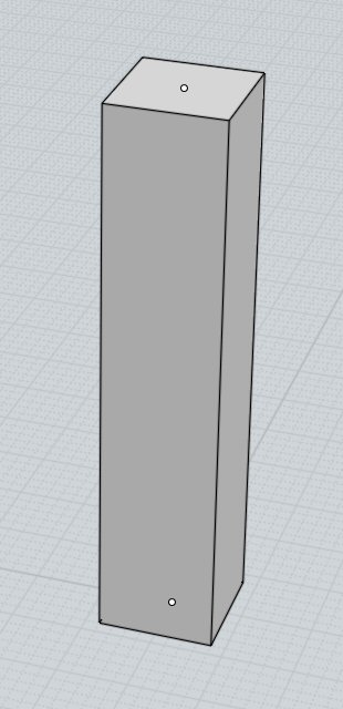
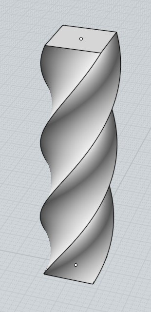
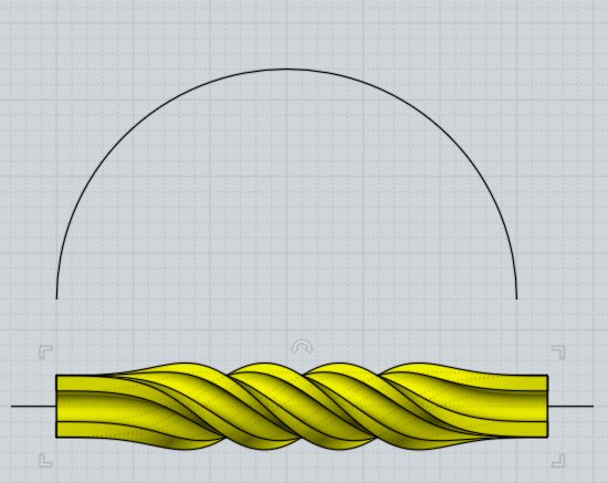
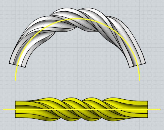
You can use curve-to-curve flow to bend an object into a circular shape by using a straight line through the object as the base curve, and a circular arc as the target curve:

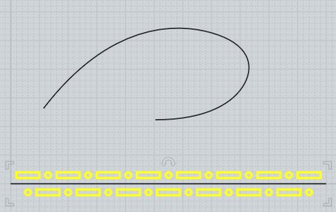
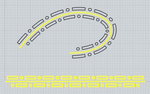
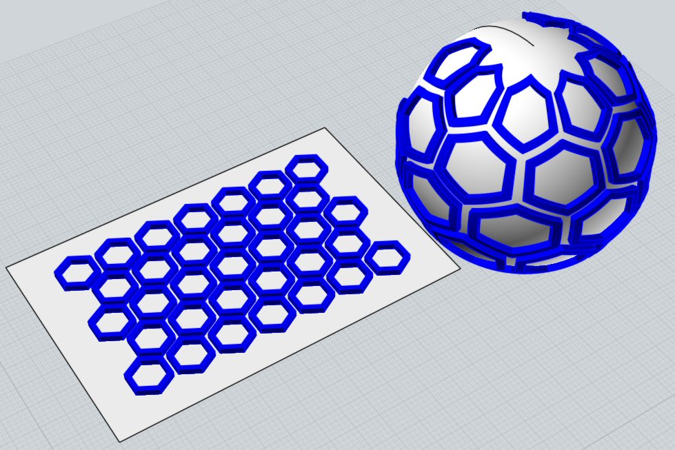
Deforming a pattern created with Transform > Array tools onto a curved shape:

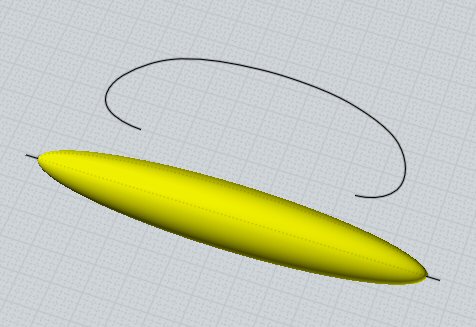
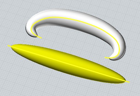
Deforming an ellipsoid into a hook shape:

A helix can be deformed to follow a curve to make a path for a phone cord sweep:

Sometimes it can be useful to position objects vertically above the curves, for example here text positioned vertically above the base line is wrapped into a cylinder shape by using a circle as the target curve:


For Flow surface-to-surface mode, start by selecting the objects you want to deform, then run the Transform > Deform > Flow command, then click on the base surface followed by a click on the target surface. Usually the base surface is a flat plane running underneath or through the middle of the objects and the target surface is a curved surface.

Surface-to-surface Flow has 2 different ways of working, regular mode and "Projective" mode. Regular mode works by applying objects across the entire target surface similar to texture mapping. Projective mode works by projecting onto a small region of the target object, more like applying a decal. Projective mode is activated by enabling the "Projective" checkbox that shows up in the stage where you pick the target surface. For regular mode the particular location of the base plane in relation to the target surface does not matter (but the click locations on each do matter, see below), while for Projective mode the objects to deform and base plane should be positioned above the area that receives the projection.

An example of regular surface-to-surface mode, the base plane matches to the entire width and height of the target surface:

An example of projective mode, the base plane projects down along the plane's surface normal direction onto a local area of the target object. The position and orientation of the base plane above the target object is significant in this mode:

For non projective mode, the locations that you click on both the base surface and target surface are significant and control how the horizontal and vertical directions of each surface will be matched to one another. You need to click nearby an edge of each surface, towards the start or end of the edge. The pattern will be rotated and reflected as needed to make the picked locations match with one another. If you do not click each surface with care it is easy for unwanted rotations to happen. Following is a visual example for where to pick.

In this example there is a pattern on a base plane that we want to put on the cylinder:

Note that before doing the Flow only the objects to be deformed should be selected, the base plane running under them should not be selected yet. You will select the base plane only after starting the Flow command. At the prompt for selecting the base surface, click on the base plane nearby one of these 8 locations marked here with a red dot:

Those 8 locations are spots along an edge towards the start or end of the edge. You do not want to click exactly on the corner of the base surface because you want to target an edge and clicking directly on the corner creates ambiguity between the 2 different edges that are connected to that corner. You can use any one of these 8 click locations, but since in the next step you will be clicking on the equivalent spot on the target surface it can be good to use a location that is easily reachable on the target surface.

For this case, let's say you picked this location on the base surface:

Picking in that location means we are going to be controlling the upper horizontal direction of the pattern. We want that direction to map to the upper circumference of the cylinder surface, so at the next prompt to select the target surface we want to click on the cylinder surface in this spot here, near the top edge but a little ways in from the corner:

That will then produce a result like this:


For projective mode the target object can be made up of multiple joined surfaces if they are all smooth to one another.

In projective mode, rays are fired out from the base plane along the base plane's surface normals and intersected with the target object. The target object should be large enough so that these rays actually hit it and do not just fire out into empty space.

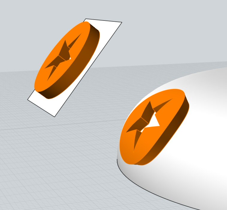
The "Rigid" option is available for all Flow modes. When enabled the "Rigid" option causes objects to be only moved and rotated into a new position (using a "Rigid body transformation") rather than the object being deformed. This will keep a sphere for example to still be a sphere in the result without it being bent or warped into a different shape. This works by deforming only a single point of at the center of the object's bounding box and then moving and rotating the object accordingly. Usually this is used to apply a pattern of small objects across the target surface.

If you plan to do a Boolean union or difference with the result of the Flow, it is usually a good idea to position the objects so that they are pushing through the base plane a little bit rather than sitting exactly flush on top of the base plane. That will then make the deformed results similarly push through the target surface rather than having pieces with overlapping surface areas that just barely touch each other. It tends to be much more difficult for the Boolean mechanisms to make sense of skimming overlapping surfaces.


Twist

Deforms objects by twisting them around an axis line.

The Twist command starts by picking 2 points which defines the twist axis.

By default the twist will apply uniformly and extend through the axis direction:

If the "Limit to axis" option is set, the twist will only be applied between the start and end points of the axis, with no twisting happening outside that region. When "Limit to axis" is enabled, the "Ease in" and "Ease out" options control how quickly the twist ramps up from the start or ramps down towards the end. Here's an example with "Limit to axis" enabled, note how at the ends there is no twisting:


Back to reference index    Prev page    Next page


© 2014 Triple Squid Software Design