Show messages:
1-19
20-39
40-59
60-79
80-99
100-119
120-129
From: Michael Gibson
Hi Gord,
re:
> Yes, it was network surface then boolean joined.
It looks like there are just a couple of spots where the endpoints don't touch. It would probably be a good idea after you construct one of these networks that you want to join to other straight parts, to edit surface control points and ensure the end control points are all trued up to be flat so the ends will be planar.
It's probably things waving around just a little bit out of being planar that is causing enough misalignment to be problematic.
> It's not repairable then?
It might be, I'll take a crack at it.
- Michael
From: Gord (NEOMEGA)
Appreciate it, thanks!
Is there a scrip I can run to allow me to see these problem areas highlighted larger? I use N, but it only shows the whole edge.
G
From: Michael Gibson
Hi Gord, there isn't any script for that, you just zoom in closely especially on corner areas where things join up. You can use the "Zoom area" tool to zoom in centered on a specific spot.
- Michael
From: Michael Gibson
Hi Gord, here is a stern piece which should be all trued up. I think this could use it here too though:

- Michael
Attachments:
 puffer1.2_trued.3dm
Image Attachments:
gord_needs_truing1.jpg
From: Michael Gibson
Hi Gord, I guess I planarized a little bit too much, I guess I should not have pulled this one up to be planar:

I was kind of thinking the upper surface wanted to be a simple straight extrusion.
- Michael
Image Attachments:
gord_planar1.jpg
From: Colin
Hi Gord,
Your constant issues with lines not meeting or touching makes me wonder whether you have "Object Snap" switched "ON"..?
If not, then may be that could help to explain a lot of your issues?
HTH, Colin
From: Gord (NEOMEGA)
Hi.
Thanks, I thought I did do - see the screenshot. Must I alter numbers somewhere?
Gord
Image Attachments:
Screenshot 2020-06-10 at 08.39.19.png
From: Frenchy Pilou (PILOU)
Funny! Never used even don't remember that is existing! :)
Maybe because i don't use millimeter as unities
Seems all is enabled!

From: corchet


gaps and a huge amount of points on curves ... don' t forget to rebuild
the central part have issues ... lonely faces .... better to contruct this as an extrusion + boolean hole
and 2 half hulls ... union give the baby solid
i add a round piece ... à l'avant qui fend les flots ;) ( 3dm joined )
ps i can't reproduce the exact shape of your hull ... cause you post the result of the network and not the curves needed to built it ;)
From: Gord (NEOMEGA)
That's awesome Michael! I have now added the raised plate that covers the join as it looks like it grew there! Many thanks!
G
From: Michael Gibson
Hi Gord, so is that going to work ok for you? Are there other problems to fix still?
So I think one problematic thing in your original one is the alignment between these pieces here:

The one on the left looks like it's trimmed off from a horizontal line:

Then the one on the right is the natural end of a Network surface:

The problem is that even if this edge:

And this edge:

Are both on the same plane that isn't going to be enough for them to get glued together well. The edge on the left coming from a trim that is interior to the surface while the one on the right coming from a curve used in Network is not going to guarantee that the shapes are going to be close enough together.
It's good for these juncture areas to be formed either by being constructed off of the same end curves, or by being intersected with each other. One coming from a trim and the other from a separate curve is not going to be good.
So if you then build separate block chunks out of these things and then try to boolean them together it's going to be something similar to this (shown exaggerated here):

And if they are pretty close to the same shape but not close enough to actually merge together, those little "shelf" pieces above are going to be really skinny slivery things which you don't want to have.
That's one of the ways things can actually get worse when things are really pretty close to matching up but just not quite enough.
The other possibility to get things like this glued together that are not quite aligned is instead of making 2 blocks right up next to each other you could leave some empty space between them and put in a transition surface like a Loft or blend between them.
- Michael
Image Attachments:
gord_join1.jpg
gord_join2.jpg
gord_join3.jpg
gord_join4.jpg
gord_join5.jpg
gord_join6.jpg
From: Gord (NEOMEGA)
That looks good now! I need to find how to get surface aligned manually. So you can't join solids and surfaces, but I still don't know why it gets out of square after I draw it on perp. lines.
Thanks, I'm sure I'll come across some other issues when my skills run out again!
G
From: Gord (NEOMEGA)
If I wanted to add a plate effect, where the thing is covered with plates but some standing slightly proud. How could that be done?
G
From: Frenchy Pilou (PILOU)
Depending if you really want the physical material effect or just at the rendering ?
Only material

or simulated by textures
From: Michael Gibson
Hi Gord,
re:
> If I wanted to add a plate effect, where the thing is covered with plates but some
> standing slightly proud. How could that be done?
Do you maybe have an image showing something similar to give a better idea of what you want?
- Michael
From: Gord (NEOMEGA)
This sort of thing?
Image Attachments:
Screenshot 2020-06-10 at 23.06.11.png
From: Michael Gibson
Hi Gord, something like that would usually be applied as some kind of texture map in a rendering program rather than directly modeled.
What are you planning on doing with this model, did you say something about 3D printing it?
- Michael
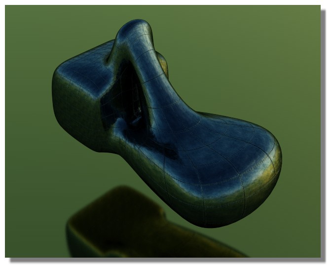
From: Michael Gibson
Hi Gord, one way you can try for plating is modeling some flat plate objects and then map them onto your surfaces using Transform > Deform > Flow.
http://moi3d.com/3.0/docs/moi_command_reference8.htm#flow

But if your Network surface has any areas where curves squished together it will also squish the plating there as well with this method.
Also there are some other programs like 3D Coat that are focused on applying bumpy details onto an object by painting directly on it, that can be a good way to add detailing like this too.
- Michael
Attachments:
puffer_flow_3dm.zip
Image Attachments:
gord_plating.jpg
From: corchet


draw a grid ( straight lines or curves ) trim the unnecessary segments
place the grid ( or the grids ) in a front view ( the segments of the grid are trimmed ... separate )
save the file ( sometimes it's buggy )
project on the boat ... depending of the complexity it may crash
trim the result ( projected grid + boat )
now you have separate plates ( flat ) select them and apply a thin shell
and a little chamfer
copy the plates ( in whole or part ) you can easily add rivets or aging the surface with scratches etc ...
From: corchet
3dm joined
Show messages:
1-19
20-39
40-59
60-79
80-99
100-119
120-129