Show messages:
1-2
3-22
23-42
43-56
From: Gord (NEOMEGA)
Sorry, not sure if I understand this?
G
From: Anthony (PROP_DESIGN)
I've been waiting for MoI v4 to be released, so I can switch from Rhino v5. I can say that in Rhino v5, you have to flip the direction of the last profile curve (almost all the time). Rhino seldom gets the orientation right. The other problem Rhino has is it often doesn't have the same end points for the profiles. So you have to find a place that exists on all the profiles to re-orient the loft direction and location. So my suggestion would be try and see if one of the direction arrows has been flipped. Also check that each loft starts at the same point on the profiles.
Also, in Rhino v5, you can loft with a rail. That will help with the above issues. Not sure if MoI has a similar option.
From: Frenchy Pilou (PILOU)
...and the bottom will be problematic
As you see your points are not regular...
Maybe better to make the global hull form without stern (?) then make a boolean with it...
From: Anthony (PROP_DESIGN)
oh i missed your attachment. yeah looking at your model what i would do is have all those cross sections be one curve instead of two. the thick feature running along the middle i would add afterwards. the way it's setup now is rather difficult to do anything with.
From: Gord (NEOMEGA)
I can get the hull done until the bow and stern, then it goes wrong. Apologies, but I'm very new to CAD, so technical references and jargon is lost on me though!
Image Attachments:
 Screenshot 2019-12-08 at 22.54.24.png
Screenshot 2019-12-08 at 22.54.55.png
Screenshot 2019-12-08 at 22.54.24.png
Screenshot 2019-12-08 at 22.54.55.png
From: Anthony (PROP_DESIGN)
that's great. more than i could do with it. rhino 5 doesn't like it much. the techniques i was thinking of don't work with the way it's setup. it looks like you are really close though. but like i said i would make all those cross-sections one curve instead of two. then i think your loft will work. the thick center portion you can make separate with an extrude. if you want you could join them together after. i'm not that great with cad either. so i understand. it can take a lot of trial and error.
i should add that if you make the thick portion from an extrude and want to join it to the hull, you'll want an overlap. you can trim the thick portion with the hull then join them. if they don't overlap then you will have problems trying to join stuff usually.
From: Michael Gibson
Hi Gord, ship hulls are a quite advanced and difficult area, it's not a simple task.
It's probably best to use the Loft style = Loose option. If you try to use a regular loft that makes the surface go directly through every section you will need to have a smaller amount of changes between each section. Having a lot of sections while simultaneously using the "directly through" style, with some sudden changes will result in a stressed surface like you are seeing.
Do you possibly have an image reference of what it is supposed to look like?
Some resources that you might check out:
Discussions on ship hull techniques on this forum here:
http://moi3d.com/forum/index.php?webtag=MOI&msg=3814.1
http://moi3d.com/forum/index.php?webtag=MOI&msg=1568.35
Some other tutorials:
https://www.rhino3d.com/resources/737
https://www.youtube.com/watch?v=3XkdIsleAqY
- Michael
From: Frenchy Pilou (PILOU)
And don't miss this free true Gem for the technical aspects! :) (maybe a little more complex than Moi! ;)
http://www.polycad.co.uk
(ps I have made the French translation! Maybe my biggest! :D
http://moiscript.weebly.com/polycad.html
Damned seen that he has made new things since 2 years!
I will update the next year! :)
From: Anthony (PROP_DESIGN)
i looked at the geometry some more. unfortunately, there are a lot of things that would need to change. one thing to consider is all the sharp corners in your profiles. that's not a realistic surface. meaning, it can't be built like that. so you would want to put in the radius values of the real thing. i went to start rebuilding and joining the curves, but there is just a lot not quite right. you have the general idea though. i think the loft isn't working out in rhino due to all the pieces of each profile. so they at least need a rebuild. but that becomes problematic given the structure. this should be doable though. just needs to be redone with different curves. once you get the hull surface. you can do an offset if you want it to have thickness. the part running down the middle you can do with one curve. it doesn't need to follow the hull shape. it can go straight through the hull end to end. then you would union, join, boolean depending what you have.
From: Gord (NEOMEGA)
Thanks! Looks like I started at a high bar too soon.
I already made all the masters for a kit of a Hurricane Catapult using MOI (see
https://www.neomega-resin.com/cam-ship-hurricat-catapult-section-997-p.asp ), and thought time for the next level...
It started as a test to see if I had the skills to translate the lines drawing to a CAD model. (I'm a professional modelmaker, so I know how I would do it in the real world) But it seems that odd things effect other things. I'm not a trained computer user, so get lost fast!
I have a model of a tug to build early next year and was hoping this could be a faster way......
Image Attachments:
VIC 32 Sheet 2.jpg
From: Gord (NEOMEGA)
I see no other way of getting the frame data in other than tracing it with the freeform curve tool?
From: Michael Gibson
Hi Gord,
re:
> I see no other way of getting the frame data in other than tracing it with the freeform curve tool?
Yes, that's correct you would need to trace that, there isn't anything like a bitmap image to structured curve automatic tracer if that's what you mean.
Do you happen to also have any 3D exterior photos? The part that is not so clear to me is the stern. It's going to be difficult to make the stern station to be such a shorter curve than the rest. That will add stress to a loft surface when one section is suddenly significantly different in size from all the others. So one thing to do in that type of situation is to make the initial surface to be extended so that it is more regular and then you cut pieces of that extended surface away using Edit > Trim or booleans. You usually want to do that kind of extended and regularized surface with cuts later on rather than trying to build the initial surface directly to an irregular boundary.
- Michael
From: Gord (NEOMEGA)
I get the same issues on a real model having to get the material to suddenly sharpen up at the stern!
G
Image Attachments:
Screenshot 2019-12-09 at 09.50.51.png
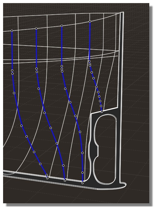
From: Anthony (PROP_DESIGN)
from what i can tell your method is right. it's just the loft takes the structure of your curves pretty much literally. you can use some loft settings to basically curve fit them, but then you loose your design intent. what i saw with your curves is the one near the middle had a much different structure than the others. so this throws the loft way off. the reason i brought up the sharp (90 deg bends) is that really makes the curve fit have problems. it makes waves in them. so it's best to not have a 90 bend in any of the profile curves. one thing as a newbie you might want to get familiar with is the rebuild command. that functions a lot like the loft options. so once you get one profile curve in, try the rebuild command to see what it does to your curves. but, if you don't want to loose any design intent, you won't want to use rebuild or the loft simplification options. in that case you need the profiles to all be structured fairly similarly. which means the profile curves all have points and breaks in roughly the same positions.
i attached a pic, showing what i mean, about the curve structures affect on the loft command. when the curves have more closely related structure you don't have a loft that looks like that.
i attached a second pic where i took out all the sharp 90 bends and did a rebuild on all curves with 20 points and a 3rd order curve fit. you can see the loft is nice and goes end to end like you want.
From: Barry-H
Hi,
did some work on the curves removed the right angles and added some extra curves at the rear.
I extended the loft curves and then used the loose loft trimmed top to shape required.
Having then created a solid Boolean diff the rear and filleted.
Not sure its accurate enough for your model ?
Cheers
Barry
.png)
.png)
Image Attachments:
Screenshot (354).png
Screenshot (355).png
From: Gord (NEOMEGA)
Thanks! Looks good.
First, where is the rebuild command, how to I get that? What does it do?
Also where are the 90 deg bends? I wasn't aware I had any.
So, I need to trace the frames using a similar number of points on each one. I need to extend the frames up more, then chop it off at the end to get the bulwark rail shape.?
G
From: Gord (NEOMEGA)
WOW! Thanks Barry!
That's what I was trying to get.
Where did you get the extra curves from? How did you do the curve work, and why?
I wish someone would do a stage by stage tutorial of this sort of thing. I find it much easier to follow if I can follow along each part as it's being done.
Thanks!
G
From: Anthony (PROP_DESIGN)
someone else will have to say where the rebuild command is for MoI v3 and v4. i'm not sure. i know it has one though.
the 90 bends are at the bottom on various profiles. not all of them have them. i would probably add in a radius to them if it where me. unless they are really there. so if you have two different pieces of wood for instance. but in that case i would create the flat sections separately from the curved ones.
you don't have to keep an even number of points. that might be impossible in some cases. but if you can do it, it's worthwhile. with the propellers and fan blades i make, i can keep an even number of points. so the lofts work out good. your ship hull is a lot more complicated. you might have to rely on the rebuild command. the only thing is, it's a curve fit. so you loose a little bit of accuracy. however, the loft is also a curve fit. so you can loose accuracy there too. it really depends on what profiles you are working with. for me, i can get the loft to exactly match the profiles. when i was working with your curves, that didn't seem possible.
you had some tricky areas and it looks like Barry got much better results than i did. i got stuck near the rear. his tips seem like good ones to try.
From: Michael Gibson
Hi Gord,
re:
> First, where is the rebuild command, how to I get that? What does it do?
The rebuild command doesn't have a button in the UI, you can launch it by either setting up a keyboard shortcut or by typing the Tab key to put focus in the XYZ input box and then type rebuild and push enter. Some info on it here:
http://moi3d.com/3.0/docs/moi_command_reference10.htm#rebuild
It probably isn't needed for your case here, Loft will usually already incorporate a rebuild of the profile in it anyway.
> So, I need to trace the frames using a similar number of points on each one. I need to extend
> the frames up more, then chop it off at the end to get the bulwark rail shape.?
I wouldn't worry about the similar number of points so much but some of the key things are try to keep things as uniform as possible so extending things to have similar lengths is better than having them suddenly become shorter and irregular areas are better to cut out afterwards instead of attempting to build a surface directly to a detailed boundary rather than a simple boundary.
Barry's example above of making a simpler extended surface and then trimming away some areas is good, and also I recommend using Loft style = "loose" like he mentions as well.
The "loose" loft style will only force the surface to go directly through the start and end profile. The ones in the middle will generally guide the shape but not be forced to go directly through them. This makes a very much more relaxed and smoother surface at the expense of accuracy. You can increase the accuracy by having more profiles. With normal non-loose loft it is easy to make a very stressed and lumpy result, with regular loft you need to use fewer profiles to reduce over constraining the surface.
If you need more accuracy than you can get with a loose loft then you're probably looking at needing to divide things up into many surfaces instead of trying to use just one single surface. This increases accuracy but now you will have a different problem that it's hard to make each surface fragment to look like it's all one smooth surface. It will generally take a lot more time and effort to try that approach.
- Michael
From: Gord (NEOMEGA)
Thanks, good info here.
I think I'll try again from the lined drawing and retrace from square one. As I said, this was a test piece anyway. I was told by an America's Cup yacht designer '..never be tempted to keep a mistake just because you took a lot of time making it'...
G
Show messages:
1-2
3-22
23-42
43-56