Show messages:
1-20
21-40
41-58
From: Michael Gibson
Hi Bravlin,
re:
> I can't understand what exactly cause the problem with this shape.
Well a few different things - too much variation in shaping between stations, like you have tight bends in the corners and then those collapse down to a pole point for the next station. There shouldn't be so much variation between profiles.
When collapsing down to a pole it's best for the shape to resemble a circle before the pole, something more like the attached file. But overall it's not a feasible shape to try and do with one single surface with poles.
Little skinny pieces are because of sharp corners not being aligned to the other direction's curves:


> The result shape on a picture is a combination of extrude, trim and loft.
> But if you look on it, shape lack of continuity and smoothness on edges.
Can you post the model file so I can get a better look at it?
> But for more square like shapes that also have smooth edges and tilt (so they not easy to
> trim or extrude) i still don't know what to do.
You build an extrusion that is straight and has flat ends initially, then introduce tilt by cutting it with a side profile, something like:


- Michael
Attachments:
 MQ_005_2.3dm
Image Attachments:
BravlinNetwork1.jpg
BravlinNetwork2.jpg
Bravlin_boolean1.jpg
Bravlin_boolean2.jpg
Bravlin_boolean3.jpg
Bravlin_boolean4.jpg
From: Michael Gibson
And if you wanted to fillet it you'd also generally avoid building these tight bends into the profile to start with, since that will limit the fillet to have to be smaller than that tight bend to avoid bunching up on itself:

- Michael
Image Attachments:
Bravlin_boolean5.jpg
From: Bravlin
>you have tight bends in the corners and then those collapse down to a pole point for the next station.
Sorry i am not sure if i understand it right. I tried to understand what you mean from project file you provide, but i don't understand what those circles mean.
Oh maybe you mean this difference in shapes ? Yes the profile in center should have the shape of a rail curve flatten.

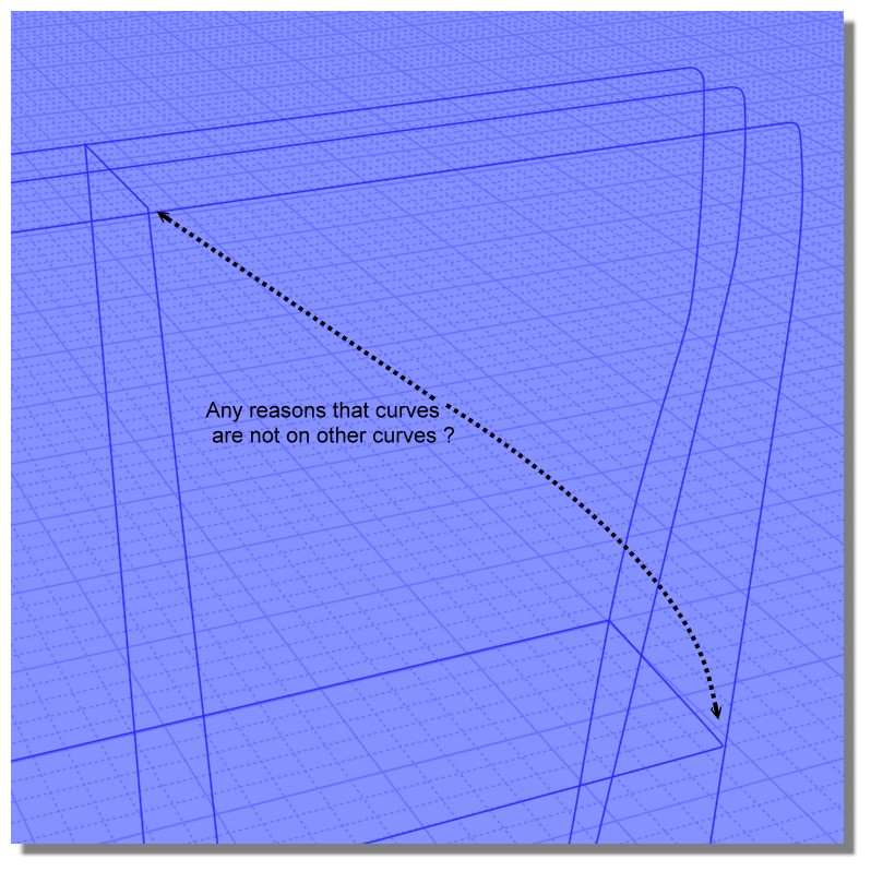
>Little skinny pieces are because of sharp corners not being aligned.
How they should be aligned ? I checked all profile curves (except rails) to doesn't have tilt.
I also tried to build them such a way so they touch rail curves with control points but it doesn't help much.
I attached a project file with result shape i construct with extrude, loft, shamfer and fillet.
> But for more square like shapes that also have smooth edges and tilt (so they not easy to trim or extrude) i still don't know what to do.
This one in result have sharp edge here.

And if you try to create tilt on a rounded corner part by trimming or extrude you lose roundness.

You may create loft surface (not solid) and boolean-merge it. But the result edge that connect loft part and extruded part also will be sharp.

Attachments:
MQ_0051.3dm
Image Attachments:
PIC003.png
PIC004.png
PIC005.png
PIC006.png
From: Frenchy Pilou (PILOU)
About your first post for this object...
If they are not some "patch" or functions (Trim etc...)will be impossible... ;)
From: Frenchy Pilou (PILOU)
Else before some deformation cage :)
We "Separate" a surface (s) from a volume and we "Add points" to it (Edit Menu / Add Pts)
This makes it like a deformation cage where you just have to move the Control Points!
Points can only be added on one surface individually!
However, you can then move the Control Points from several surfaces at once!
Edit / View Points function activated of course! You can use the Edit / "Hide" and "Lock" functions
At the end, everything is grouped into a single "solid" volume (if the points of each adjoining face are "confused"!
For move points with some mirror effect with Scale function ;)
From: Bravlin
At first i create profile curves that lies exactly on rail curves.
But its not the main problem. The result shape looks messy.
From: Michael Gibson
> >Little skinny pieces are because of sharp corners not being aligned.
> How they should be aligned ? I checked all profile curves (except rails) to doesn't have tilt.
They should align by the curves touching each other at sharp corner areas.
Currently the closest points between your curves in that area is here:

So the generated surface is going to match up the closest points between those curves, and since that is not at the sharp point that will make a skinny fragment there when it additionally passes through the sharp area.
> I also tried to build them such a way so they touch rail curves with control points but it doesn't help much.
Touching control points is irrelevant, it's the actual body of the curves that would need to touch.
> And if you try to create tilt on a rounded corner part by trimming or extrude you lose roundness.
If you want your cut to have roundness you could build a rounded cutting surface using something other than extrude, like sweep. Then you'd fillet sharp edges to round them off.
But if the type of work that you want to do is similar to chipping away fragments of an initially blocky object while keeping everything smooth, that's really something more suited for ZBrush or 3D Coat's functionality. It's not a great fit for NURBS modeling.
- Michael
Image Attachments:
BravlinNetwork3.jpg
From: Bravlin
Michael,
so if i understand it right there no need to create curve profiles so they lies with control point exactly on a rail profile.
You just need touch it somewhere(in other words you need intersection).
Mr. PILOU,
and there is no smooth operator plugin or script and no brushes for Moi right ?
Only click and drag points ? Maybe there is a grow selection script for points like we have for faces ?
From: Michael Gibson
Hi Bravlin, yes for the case of having sharp corners, the other direction curves should intersect with the corner location.
On other cases where there are not sharp corners it's usually ok for the curves to just come close to each other.
But that's just one issue - it's still just not going to work very well to try and build something like that out of one single network surface.
- Michael
From: Frenchy Pilou (PILOU)
<< Smooth operator
I believe that a nurbs surface is by definition a "smooth" surface :)
If you want modify it use my method above or similar and use some moves of the Edit Frame with some Control Points selected
<< No Brush
I don't believe for the moment
<< Grow Selection
for the moment only for faces from Edge or Face by Max Smirnov
A radial selection will be a fine start ;)
From: Bravlin
> I believe that a nurbs surface is by definition a "smooth" surface :)
Nice one ;) We still need to move control points to make surface smoother.
Something similar to smooth deformer in XSI or a brush that distribute parameter (smooth deformer weights) could be pretty helpful.
From: Frenchy Pilou (PILOU)
<< We still need to move control points to make surface smoother.
Maybe there is yet something with the Node Editor! Ask it on their thread!
https://moi3d.com/forum/messages.php?webtag=MOI&msg=7777.1
(but your are not on the Nurbs' spirit ! ;)
From: Michael Gibson
Hi Bravlin, often it is not feasible with NURBS to smooth things out using control point editing because of how trim curves and "underlying surfaces" work.
When you do a boolean operation, surface control points do not change at all, instead the trim curves on surfaces are what changes. Trim curves mark areas areas of a surface as holes and in a model with trimmed surfaces you generally can't manipulate surface control points without opening up a hole.
There is some illustration of that here:
http://moi3d.com/faq#Q:_Why_does_show_points_work_for_some_objects_but_not_others.3F
It's a very different type of structure than polygon modeling.
- Michael
From: Bravlin
So that's why boolean great in NURBS and such a crap in poly modeling.

So the more NURBS-like approach is to build shapes like so ?
Create profile curves, extrude curved surfaces, manipulate points (in this example i
use flow as deformer to bend surfaces) to get shapes you want. And trim it in the end.
Attachments:
MQ_03.3dm
Image Attachments:
PIC007.png
From: Frenchy Pilou (PILOU)
Yes you arrive to the Nurbs spirit!
Micro deformation is Polymodeling
Macro deformation in Nurbs modeling! ;)
From: Michael Gibson
Hi Bravlin, yup that is correct - with polygon booleans where there isn't any concept of an "underlying surface", things get fragmented into little bits pretty easily.
With NURBS modeling that doesn't happen or at least happens much less frequently and that's a major factor for why booleans with NURBS work well.
There are some other things too like it helps in many situations that NURBS can represent things like an exact sphere with one surface instead of lots of little pieces and then intersections between a sphere and a plane can be handled as a special case with an exact result.
The tradeoff is that trim edges do not necessarily align with the control point structure of the underlying surface and so you can't modify an object by pulling edge points around like you can in poly modeling except in special cases.
So that also means that if you're not using booleans in your NURBS modeling approach you are also not really leveraging the strongest area that it offers.
- Michael
From: Bravlin
Q_04:
Hi guys. Got another question.
Today it's not about surfaces and shapes.
It's about proportions and scale. I have this kind of a bended shape. It was bent by "Flow" deformer.
Now it has become necessary to make this shape thinner. But if i use scale operator we lose src proportions of this shape.
I assume that Flow operator may help with it. But i can't understand which surface to use for such case.
I don't have src surfaces that i used for shape bending.
If scale operator can solve this problem i dunno how to use it right?

Attachments:
MQ_04.3dm
Image Attachments:
PIC001.png
From: Michael Gibson
Hi Bravlin, it's usually best to do such edits on your unbent shape and then do a new Flow with your updated object.
It is possible though to do a kind of "scale from center path" operation with Flow, to do that you would make a Sweep of a line profile:

Along a central rail curve:

That will be the base surface for the flow. Then make a narrower sweep surface using a shorter line along the same rail, that will be the target surface for the Flow. An example result is attached.
- Michael
Attachments:
MQ_04_2_3dm.zip
Image Attachments:
Bravlin_flow_scale1.jpg
Bravlin_flow_scale2.jpg
Show messages:
1-20
21-40
41-58

