Show messages:
1-15
16-29
From: BurrMan
Almost all of the drawing and inpit type commands also work with MoI's "input field" also, which allows you full, normal mcad control of how you enter pick points. Distance, angle and coordinate placements.
You'll have to spend a few hours working there, to fit it into how you like to work. Sometimes its just directly start typing, sometimes it requires a "tab" to move from the current input field, to the one desired.....
You can find it in the help file, or asking here can get you detailed responses....
From: Rainydaylover (DIMITRI)
Burrman do you have some links where someone can find explanations and tutorials on how to access the options you mention?
From: Frenchy Pilou (PILOU)
Seems that is that ;)
http://moi3d.com/3.0/docs/moi_command_reference.htm
http://moi3d.com/3.0/docs/moi_command_reference11.htm#propertiespanel
http://moi3d.com/3.0/docs/moi_command_reference1.htm#__XYZ / Distance / Angle
etc...
From: moujiik
Hi Dimitri
Image Attachments:
 GIF.gif
From: Frenchy Pilou (PILOU)
It's that I say without animation ( because seems evident for me) :)
http://moi3d.com/forum/index.php?webtag=MOI&msg=8875.11
About deformation surface you can make something like this!
"Separate" a surface(s) from a volume and "Add points" to it (Edit Menu / Add Pts)
This makes it like a deformation cage where it is enough to move the Control Points!
Points can only be added on an individual surface!
However, you can then move the Control Points from several surfaces at once!
Edit / View Points function activated of course! You can use the Edit /"Hide" and "Lock" functions
At the end everything is grouped in a single "solid" volume (if the points on each side are "overlaped"!
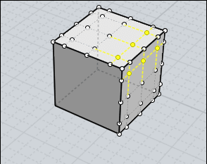
You can use the Move function and Help Lines for precise movement of the Control Point(s)!
Above from the middle of the side to the middle of the diagonal to the oposite edge.
Remark that in this case Points of edges are not selected for keep the futur solid valid!
Join at the end for remake the Solid!
Et voila an elaborated cage deformation simulator! :)
From: Michael Gibson
Hi Pilou, that's a little different than the cage deformation originally asked about - the type of thing that Dimitri was asking about was not just making a deformed cage but rather making an object (any object) contained inside of the cage to be deformed along with it.
- Michael
From: mkdm
Yes Pilou.
Michael is talking about a command like "Cage" and "CageEdit" available in Rhino (for example)

Marco (mkdm)
From: Rainydaylover (DIMITRI)
Moujik… I am aware of the think you say but as I said before, I would prefer not to begin with a ‘1’ unit indication but with the actual diameter length value and change it.
Of course, Ed’s help was immensely helpful but the need for a proportional scaling by altering the dimension of an object's specific area (say the finger hole of a ring) remains. I would like to change, for example, a ring’s finger hole diameter which is 14 mm to 16.5 mm and have all the ring change proportionally as to its overall dimensions. Such a thing would be very helpful in some cases. Because even changing the whole ring’s dimensions –by using the upper right dialogue box (where the style and kind of object are indicated)- would require some ‘manual’ calculation for having the finger hole diameter precisely changed. But, anyway, this is not a so big problem... just putting it forth as an idea. : - )
Pilou… I do know about the method you mention but it is not the same thing. Btw, thanks for the links… very precious! : - )
Michael… to my opinion cage deformation is not a secondary need even for modeling tasks other than the jewelery related ones. It is true that in the case of jewelry it is a very central need but in many other cases too it can be a serious need. And, of course, why not making Moi, as a modeling app, a very appealing choice for jewelery design too... It does not require many things for being such an app. It is almost ready, some further refinements, here and there, and it will be superb!
And… without the slightest exaggeration, Moi is much more versatile, much more user friendly, with an incomparably clearer ui and much more approachable as to its price than Rhino. Rhino is very powerful –no doubt- but it is too back as to its ease of use in comparison to Moi. Even the viewport imaging quality of Moi is constituting by itself a high quality npr rendering solution.
I think that you must re-think about a cage reshaper’s necessity. To my opinon it is not something that can be pushed aside as a secondary need. But you know, of course, Moi is great already and we will wait gladly even for a v.5 for having the tool. : - )
From: Frenchy Pilou (PILOU)
<< that's a little different than the cage deformation originally asked about
Sure, it was a little speed simulator! :)
From: ed (EDDYF)
DIMITRI -
If you want scale a ring model to any standard ring size, do the following:
Download and install the Ring Circle Creator script. This a MoI script designed to aid in modeling rings. Based on the finger size selected, it draws the proper ring inside-diameter circle, which becomes the basis for modeling the ring. Note: If the resulting circles do not exactly match the ring size chart you are accustomed to using, you can easily edit the values inside the file RingCircle2.htm using Notepad to match.
The script for MoI ver 3 is here:
Use RingCircle2.js from:
http://moi3d.com/forum/index.php?webtag=MOI&msg=4441.10
Use RingCircle2.htm from:
http://moi3d.com/forum/index.php?webtag=MOI&msg=4441.11
Place both files in your MoI Commands folder: C:/Program Files (x86)/MoI 3.0/commands
To run the script, press the Tab key and type RingCircle2 (You can also create a shortcut key to run the script)
Look in the upper right corner of the MoI window for the Ring Options Menu. You can select the Measurement System and the Size. Click “Done”. The result will be a circle. For sake of these instructions, change the circle color to Red.
Use the Alignment tools to center your ring’s finger hole and the red circle so they are concentric.
Click on the Scale tool. Click on the ring. Click “Done”. Click once on the center point (origin) of the two circles. Click once on the edge of the ring’s finger hole. Click once on the red circle.
Your ring is now scaled to the new finger size.
Try it a couple of times and you’ll find it goes very fast.
Ed Ferguson
From: Michael Gibson
Hi Pilou,
> Sure, it was a little speed simulator! :)
Ok, but it's good to be clear that it's not a technique that does what this thread is about though. That method you use of editing surface control points directly is only going to work on something like a box. On more complex shapes especially ones that have booleaned pieces it's not going to work.
- Michael
From: Michael Gibson
Hi Dimitri,
> Moujik… I am aware of the think you say but as I said before, I would prefer not to begin with a ‘1’ unit
> indication but with the actual diameter length value and change it.
Please look at Moujik's example more closely because it's doing exactly what you're asking.
In that example he's not using the '1' unit indication scale factor input at all, he's using the "reference points" function in the Scale command to apply a scale between 2 distances. That's a feature in the Scale command that exists to handle exactly what you're asking for, so you can measure an existing length in your model (in this case the diameter length as you can see in Moujik's example) and match it to another desired length (in Moujik's example it's a point placed using distance constraint).
> Because even changing the whole ring’s dimensions –by using the upper right dialogue box
> (where the style and kind of object are indicated)- would require some ‘manual’ calculation
> for having the finger hole diameter precisely changed. But, anyway, this is not a so big
> problem... just putting it forth as an idea. : - )
This is exactly what using reference points in the Scale commands already provide. Instead of entering in a scale factor you can choose 2 lengths and MoI will calculate the needed scale factor for you. You can choose the lengths by snapping on to existing points in your model (good for capturing the existing diameter of your ring for example), or to enter in a numeric length use distance constraint which works in any drawing command to place a point at a specific distance away from a base point.
- Michael
From: Michael Gibson
Hi Dimitri, also using the reference points in Transform > Scale command to calculate the needed scale factor for you is covered in detail in the help file here:
http://moi3d.com/3.0/docs/moi_command_reference8.htm#scale
- Michael
From: Rainydaylover (DIMITRI)
Ed... I have already the script you refer. Thanks, however, for reminding it.
Michael... thanks for your so dedicated answers, they are very precious!
Show messages:
1-15
16-29