Automatic process
 1-20  21-40  41-53

Previous
Next
 From:  Michael Gibson
3666.41 In reply to 3666.40 
Hi Sharif, could you possibly simplify your file to contain just 1 surface and 1 curve that you want to cut it with? That would help to make it easier to understand what you are trying to do there.

One thing to note is that to cut a surface with a curve, the curve has to fully divide the surface into separate pieces.

For example here is a plane and a line, the plane cannot be trimmed by the line because it does not clearly divide the plane into different pieces:


Here I have enlarged the line somewhat, so that maybe it kind of looks like it would almost divide the plane, however it actually still does not divide it and will still have the exact same problem as above:


You may be running into something like that.

- Michael

  Reply Reply More Options
Post Options
Reply as PM Reply as PM
Print Print
Mark as unread Mark as unread
Relationship Relationship
IP Logged

Previous
Next
 From:  BurrMan
3666.42 In reply to 3666.40 
I think you are refering to all those little fragmented pieces that arent supposed to be in the trimmed facets. WHen you do the cross trim. you will want to make the trim curves "planar" and move them away from the surface a bit. This will allow them to trim the surface properly. AND what Michael said about making them be larger than the surface.

So if these were the trim curves:


I can go to the right view and use the edit frame to flatten (Planar) them out:


Then I would have a configuration like this for trimming:


WHen I run trim on these planar and extended curves. they trim without those little fragments:


Sometimes you have to work your trim curves a bit because MoI does this kind of "automatic projection/extrusion" thing and this can cause these self intersecting anomolies when the trim curves kindof float in 3d and trim in "Multiple directions"...

Here's your file back just before the trim. I just flattened out those trim curves.

EDITED: 19 Jun 2012 by BURRMAN

  Reply Reply More Options
Post Options
Reply as PM Reply as PM
Print Print
Mark as unread Mark as unread
Relationship Relationship
IP Logged

Previous
Next
 From:  Sharif (SR13765)
3666.43 In reply to 3666.42 
Hi Michael and BurrMan;

Thanks for the responses. What I bascally did, I creaed those curves via LineWeb Tool, Then I made a surface from them via network command, then I used the trim command to divide the surface.

Well I did another method as follow and it worked without moving the curves:

1. Create a loft surface between two curves
2. Create curves on the surface with LineWeb Tool in both dirction
3. Trim the surface with the LineWeb tool curves and worked like a charm. See Attachment

Two more question

How do you get to the flat command?
How do you offset a curve that is on a surface on the same surface? Does the offset command works only in XY plane?

Thanks again

Sharif
Attachments:

Image Attachments:
Size: 58.9 KB, Downloaded: 31 times, Dimensions: 1006x755px
  Reply Reply More Options
Post Options
Reply as PM Reply as PM
Print Print
Mark as unread Mark as unread
Relationship Relationship
IP Logged

Previous
Next
 From:  SteveMacc (STEVEH)
3666.44 
This script is great for making railings if you combine it with the pipe script.


Attachments:

  Reply Reply More Options
Post Options
Reply as PM Reply as PM
Print Print
Mark as unread Mark as unread
Relationship Relationship
IP Logged

Previous
Next
 From:  BurrMan
3666.45 In reply to 3666.43 
"""""""""""""""How do you get to the flat command?""""""""""""

Using the edit frame. If you look in the screenshot I posted of it, you will see I circled the handle to the one side. If you grab that handle and drag it to the middle, you will get a "flat" snap, which means you have scaled everything in 1d to flat.

The trimming is supposed to work like it did for you. Just if you see it trim a bunch of weird stuff in multiple directions, you can refer to what I posted to give it a chance..


""""""""""""""How do you offset a curve that is on a surface on the same surface?""""""""""

The offset wont do a "stay on the surface" operation, but you could use projection to do this. Since you already have a curve, you can view it in one of the planar views, duplicate it (Use the flat again), move it over the amount you want, then project it onto the surface again.
  Reply Reply More Options
Post Options
Reply as PM Reply as PM
Print Print
Mark as unread Mark as unread
Relationship Relationship
IP Logged

Previous
Next
 From:  Michael Gibson
3666.46 In reply to 3666.43 
Hi Sharif,

For some more info on flat snap see here:
http://moi3d.com/2.0/docs/moi_command_reference11.htm#editframe

re: offset - yeah offset is mostly oriented towards offsetting a planar curve, and the offset happens in the same plane that the curve is in.

It is possible to offset a non-planar curve but it then happens in some pieces that use the construction plane as a frame of reference.

There isn't any way currently to offset a curve that is on a surface and keep it on the surface all in one operation. Sometimes you may want to build a tube around your curve and use the Construct > Curve > Isect command to generate intersection curves between the tube and the surface to get something like that though.

- Michael
  Reply Reply More Options
Post Options
Reply as PM Reply as PM
Print Print
Mark as unread Mark as unread
Relationship Relationship
IP Logged

Previous
Next
 From:  Sharif (SR13765)
3666.47 In reply to 3666.46 
Or perhaps I can use the Array-direction command

Thanks
  Reply Reply More Options
Post Options
Reply as PM Reply as PM
Print Print
Mark as unread Mark as unread
Relationship Relationship
IP Logged

Previous
Next
 From:  BurrMan
3666.48 In reply to 3666.47 
""""""""Or perhaps I can use the Array-direction command"""""""""""""""

Yes, in this instance it will work for those trim lines, because they are just uni-directional in nature. The paneling will be spaced properley. But there will be times when you need the curves layed out, or the spacing will become distorted. Thats where this command can make a difference over just a straight directional array.
  Reply Reply More Options
Post Options
Reply as PM Reply as PM
Print Print
Mark as unread Mark as unread
Relationship Relationship
IP Logged

Previous
Next
 From:  Frenchy Pilou (PILOU)
3666.49 
Make variable tubular structures is now a game's boy :)
LineWeb + Pipe2 http://plugmoi.voila.net/index.htm#Pipe

EDITED: 19 Jul 2010 by PILOU

  Reply Reply More Options
Post Options
Reply as PM Reply as PM
Print Print
Mark as unread Mark as unread
Relationship Relationship
IP Logged

Previous
Next
 From:  Frenchy Pilou (PILOU)
3666.50 
Can be useful for emulate Rotation along a curve ;)


---
Pilou
Is beautiful that please without concept!
My Gallery
Attachments:

  Reply Reply More Options
Post Options
Reply as PM Reply as PM
Print Print
Mark as unread Mark as unread
Relationship Relationship
IP Logged

Previous
Next
 From:  Mike K4ICY (MAJIKMIKE)
3666.51 
Here is an additional control method for using the LineWeb script:


I was working on an alternate method for creating the arcs used to make the pipes in the "bird cage" ring tutorial.

The LineWeb script was a perfect tool for this process. Basically, I have a few closed-curves to define the ring's shape and I want arcs perfectly arranged around these curves. These arcs have to flow at a sweeping angle.

[The LineWeb script - here in a previous post: http://moi3d.com/forum/index.php?webtag=MOI&msg=3666.10 ]


A problem arose where LineWeb would naturally follow the true start/end points of the target curves. I could not control where the LineWeb would construct the lines.
If there was a command or script that could reposition the start-point in a closed curve, I would like to know.
(Also, the curves made by LineWeb yielded a chaotic result, but the use of the non-UI "Flip" command on the center closed-curved fixed that issue.)

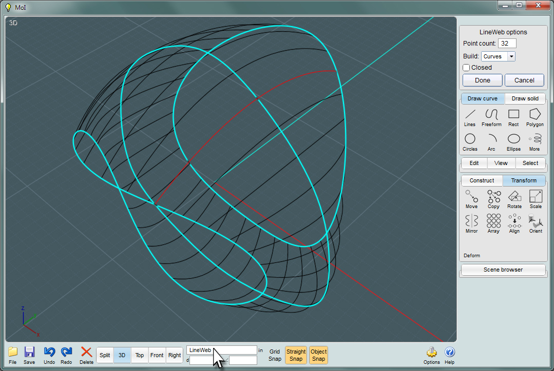
But there is an easy remedy: Use the Loft command to reposition the control points.


You'll notice here that LineWeb has created some essentially well-ordered curves that have an expected "straight" distribution.
It isn't what I wanted in this case.


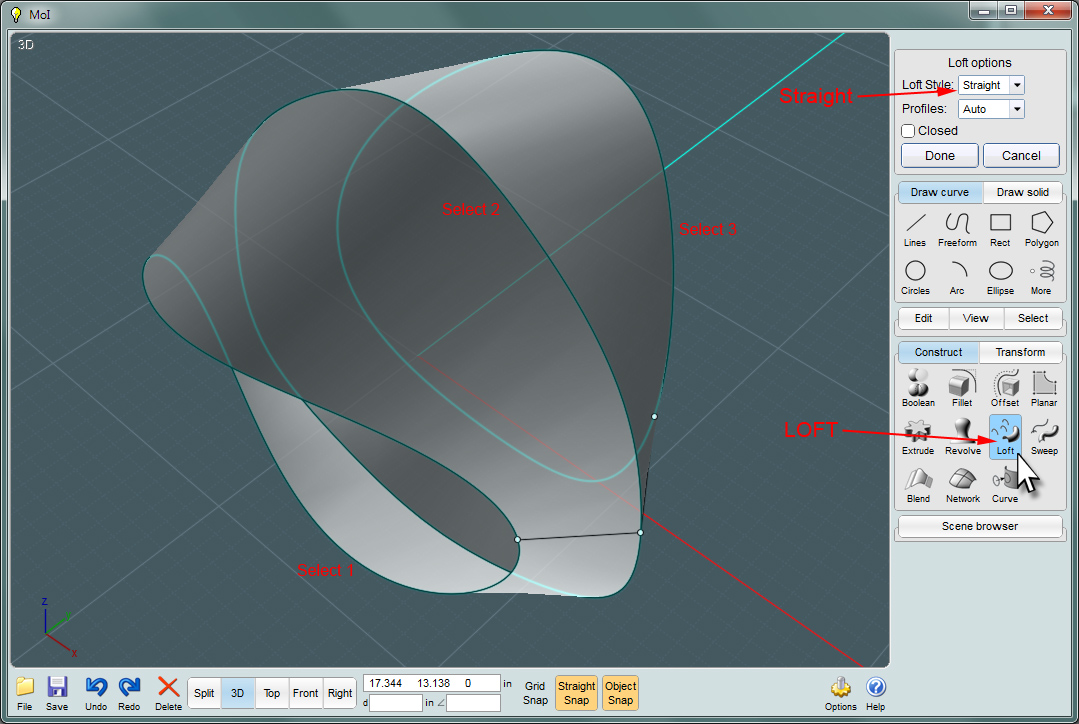
Here, I'll use the Loft command to get control over my hidden start/end control points.
Use the "Straight" option in the Loft dialog. This way, the result retains your intermediate curves. Otherwise, Loft will not recreate them.


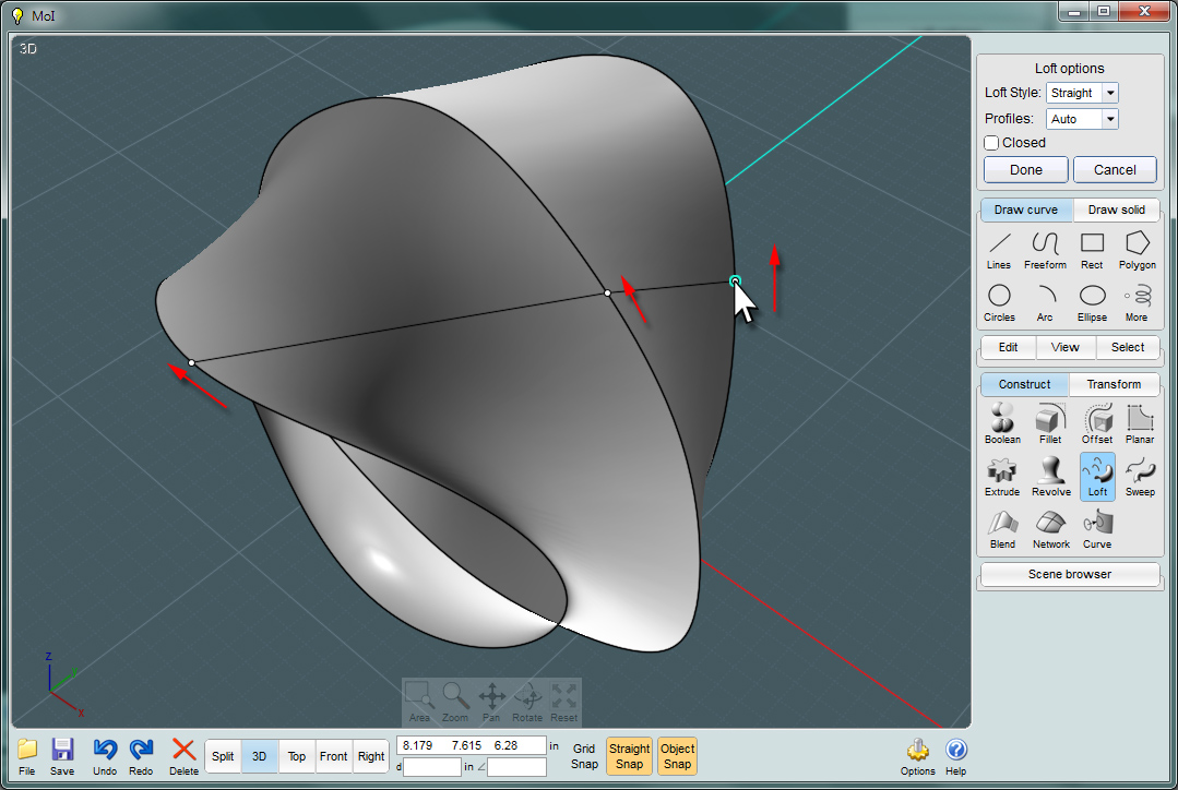
You can now reposition your control points anywhere you need them.


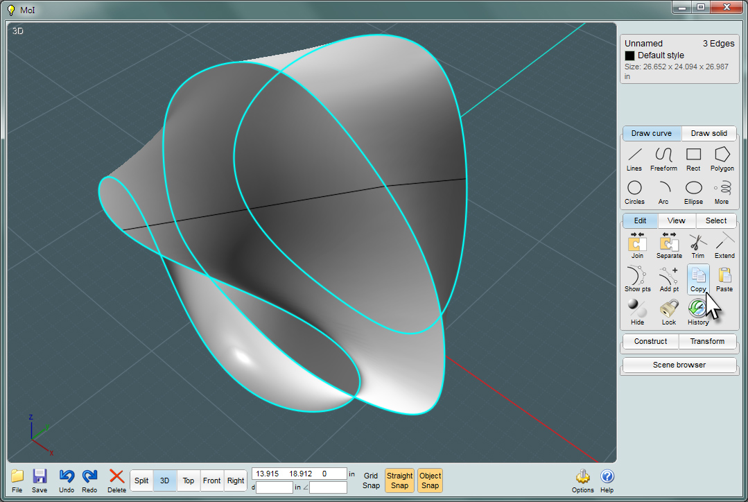
Delete your original curve as you no longer want those. Drill-select the new edge curves that define the Loft object and Copy those.
Now delete the Loft object and Paste your saved closed-curves.


Here again, you can use the LineWeb scipt. Make sure you select your closed-curves in a desired succession as you would for Loft.


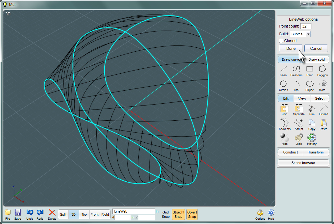
As you can see, the new LineWeb curves follow an angled sweep.
Now, I have the desired appearance for the ring made in my project.
  Reply Reply More Options
Post Options
Reply as PM Reply as PM
Print Print
Mark as unread Mark as unread
Relationship Relationship
IP Logged

Previous
Next
 From:  Rich_Art
3666.52 In reply to 3666.51 
How can I completely missed this thread...

Thanks for the script.


Peace,
Rich_Art. ;-)

| C4DLounge.eu | Our Dutch/Belgium C4D forum. |
  Reply Reply More Options
Post Options
Reply as PM Reply as PM
Print Print
Mark as unread Mark as unread
Relationship Relationship
IP Logged

Previous
 From:  Mauro (M-DYNAMICS)
3666.53 In reply to 3666.52 
..me too....thanks to you Rich,i discovered this tool ! (thanks to Michael and the guys of this thread too)
  Reply Reply More Options
Post Options
Reply as PM Reply as PM
Print Print
Mark as unread Mark as unread
Relationship Relationship
IP Logged
 

Reply to All Reply to All


Show messages:  1-20  21-40  41-53