V5 Wish List
 1-7  …  428-447  448-467  468-487  488-507  508-527  …  588-602

Previous
Next
 From:  Larry Fahnoe (FAHNOE)
10114.468 In reply to 10114.467 
Hi Michael,

> Could you describe what the challenges and limitations would be?

The challenge is primarily complexity of the script as it is trying to knit together an understanding of the model it is working on and only do a limited set of operations. One limitation is if the list of objects fed to the intersect is too broad there may be other intersections that generate points which are unrelated & this would lead toward more complexity to eliminate those points. There may be other issues I’ve not tripped over yet...

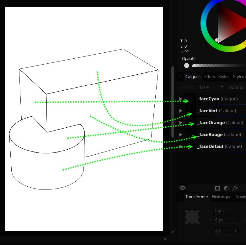
So for example, see the attached model. The structure on the right represents a building with ICF (insulated concrete form) walls which are poured. The concrete in the 4 walls is represented as a single solid and I represented the foam insulation layers in the same way. There are also solids representing drywall on the inside and siding on the outside. The goal is to cut and frame a single window on one side. To do that one needs to select only the faces that are to be cut rather than simply selecting all the wall components. The process of manually selecting only the faces associated with one wall with the UI is cumbersome and would ideally be done by the script. My script currently uses the subset boolean difference that you suggested earlier and therefore cuts windows on both sides of the building if the entire wall structure is selected (which is the result that is currently shown).

I believe I can identify the necessary faces per Peer's suggestion of using using BRep’s dropPoint(). https://moi3d.com/forum/index.php?webtag=MOI&msg=10907.5

So, to try this, draw a normal line through the wall where the window is to be cut. Then intersect the line and all the wall components. In my model the only points that result are those where the normal intersects the faces of the solids, other models might have other points. Using the points that result, I think the approach is to use dropPoint() on each BRep and then get the face from the first element of the list that is returned, then process more or less as the script is currently written. I say I think only because I’ve not gotten it working yet, but I think I can.

One of the things that I take away from looking at the scripts you include with MoI is their simplicity and elegance: many are just bits of glue that tie the UI to the various factories. Thus when my script begins to get cumbersome and I’m fumbling around trying to accomplish something, I tend to question my approach. Is there a simpler way? Hence the idea of a “nearest neighbor” GeomObject method.

If such a method existed, I would imagine that it would find and return the lowest (most elemental) objects. In this case I would imagine that it would return the nearest face intersecting the vector & from there I could build up the list of faces via subsequent calls and then do the subset boolean difference. The idea struck me as one that might also be useful for other tasks where UI selection is inconvenient, and therefore a generalized tool that would benefit the script environment.

--Larry
Attachments:

  Reply Reply More Options
Post Options
Reply as PM Reply as PM
Print Print
Mark as unread Mark as unread
Relationship Relationship
IP Logged

Previous
Next
 From:  Michael Gibson
10114.469 In reply to 10114.468 
Hi Larry,

re:
> One limitation is if the list of objects fed to the intersect is too broad there may be other
> intersections that generate points which are unrelated & this would lead toward more
> complexity to eliminate those points.

Ok, but how do you want me to implement the "nearest neighbor GeomObject method" without running into these very same issues?

At some point I would like to have an option when you're booleaning a solid with a planar curve to look at the results and only keep the cut that was closest to the curve, sort of like an automatic subset. Maybe that would help but I'm not sure when I'll be making that.

- Michael
  Reply Reply More Options
Post Options
Reply as PM Reply as PM
Print Print
Mark as unread Mark as unread
Relationship Relationship
IP Logged

Previous
Next
 From:  Larry Fahnoe (FAHNOE)
10114.470 In reply to 10114.469 
Hi Michael,

> Ok, but how do you want me to implement the "nearest neighbor GeomObject method" without running into these very same issues?

Since I don’t know much of anything about the data structures that hold the model in memory, I only have an approximate idea of how one might implement a nearest neighbor method. I infer from your question though that you'd approach it in a way similar to the intersection of the line and other objects. The image I had was of the vector acting like a sort of laser "probe" which would only illuminate the object being intersected: an intersect with a priority. In other words, the vector in the intersect operation acts to select the objects rather than the intersect returning all intersections across all objects within the set. The distance component of the vector would further limit the set of objects. The method would ultimately return the object closest to the vector's origin.

The "cut closest to the curve" part of your idea might be along similar lines.

--Larry
  Reply Reply More Options
Post Options
Reply as PM Reply as PM
Print Print
Mark as unread Mark as unread
Relationship Relationship
IP Logged

Previous
Next
 From:  Michael Gibson
10114.471 In reply to 10114.470 
Hi Larry,

re:
> The image I had was of the vector acting like a sort of laser "probe" which would only
> illuminate the object being intersected: an intersect with a priority. In other words,

There are methods like what you describe here used for raytracing renderers.

It's possible to create a type of hierarchical bounding structure around objects such that if the ray intersects an object inside one node of the bounding structure it can know that objects contained in some other further away nodes within the structure do not need to be searched.

But I don't have anything for that already prepared and there is quite a lot of work involved in setting it up and making sure it works properly.


> The "cut closest to the curve" part of your idea might be along similar lines.

It will probably be implemented fairly different from that. Probably something more like it will generate all candidate holes and then only select one to actually use.

- Michael
  Reply Reply More Options
Post Options
Reply as PM Reply as PM
Print Print
Mark as unread Mark as unread
Relationship Relationship
IP Logged

Previous
Next
 From:  pressure (PEER)
10114.472 In reply to 10114.471 
Hi Michael,

I often wish that I could edit vector graphics in MoI because it has geometric drawing tools that don't exist in graphics editors. I do this a little now, but it's arduous because the layout and layer/group structure of an SVG/AI get destroyed by being imported into MoI and then exported out again as SVG/AI. I end up having to import only 1 layer or group at a time into MoI and then use fiducial marks to get things registered again in a graphics editor.

Keeping some layer or group structure is needed so that things like stroke weight, color, dashes, fills, etc. can be set again when back in a vector graphics editor.

Maintaining layout relative to a page boundary is needed so that layout and dimensions don't change visually or for printing and also to make copy-pasting between vector files easy without going through an alignment and scaling step each time.

It looks like this sort of thing has been discussed before:

http://moi3d.com/forum/lmessages.php?webtag=MOI&msg=9889.3

http://moi3d.com/forum/index.php?webtag=MOI&msg=10774.55

Getting this working probably won't be easy, but it would shave off a bunch of tedious work.

If anyone has figured out a streamlined workflow for editing vector graphics in MoI I'd love to hear about it.
  Reply Reply More Options
Post Options
Reply as PM Reply as PM
Print Print
Mark as unread Mark as unread
Relationship Relationship
IP Logged

Previous
Next
 From:  Michael Gibson
10114.473 In reply to 10114.472 
Hi Peer,

re:
> <....>
> Maintaining layout relative to a page boundary is needed

Unfortunately there is a vast amount of work that would be needed to manage a "paper space" environment inside of MoI. I don't expect for that to happen anytime soon, perhaps never.

In general it will work better using MoI alongside a 2D vector graphics program if the data flow is more unidirectional, like you're mainly bringing data from 2D vector graphics into MoI or creating it in MoI and sending it to the vector graphics program. Frequently ping-ponging the same data back and forth is not very workable.

- Michael
  Reply Reply More Options
Post Options
Reply as PM Reply as PM
Print Print
Mark as unread Mark as unread
Relationship Relationship
IP Logged

Previous
Next
 From:  pressure (PEER)
10114.474 In reply to 10114.473 
Hi Michael,

Thank you for giving a definitive answer.

- Peer
  Reply Reply More Options
Post Options
Reply as PM Reply as PM
Print Print
Mark as unread Mark as unread
Relationship Relationship
IP Logged

Previous
Next
 From:  pressure (PEER)
10114.475 In reply to 10114.473 
Hi Michael,

Having closed paths is critical to several common tasks in technical illustration:
  1. Closed outline curve so that the outline stroke can be aligned to the outside of the path rather than along center. This avoids having a thick outline overlap the inside of an object which is important when there are fine details along the outline.
  2. Hatching clipping mask like for adding a hatch pattern to indicate that a face has been cut by a cross section plane
  3. Fills such as block shading like this example:

    https://moi3d.com/forum/lmessages.php?webtag=MOI&msg=10770.1

    which was made by hand in a vector graphics editor by drawing closed curves and then filling them.

Needing closed paths has come up before:

https://technicalillustrators.org/forum/viewtopic.php?f=1&t=211&start=7

http://moi3d.com/forum/lmessages.php?webtag=MOI&msg=6201.61

I've tried out a bunch of different ways of getting from the MoI's SVG/AI output to closed paths, but have found that Illustrator's Live Paint is the only one that works reliably. Several other vector graphics editors claim to have this capability, but they aren't reliable on MoI's vector output because of tiny geometry problems that are essentially invisible. Inkscape is reliable, but sometimes leaves a gap between the closed shape and the line art, and has other problems.

So, it would be helpful if another layer were added to MoI's SVG/AI output. This layer would contain nothing but closed paths.

A few approaches that might work:

- Peer
  Reply Reply More Options
Post Options
Reply as PM Reply as PM
Print Print
Mark as unread Mark as unread
Relationship Relationship
IP Logged

Previous
Next
 From:  Frenchy Pilou (PILOU)
10114.476 In reply to 10114.475 
And something like Affinity Designer (low cost) who reload without problem PDF format from Moi3D ?

In any 3D position in the 3D Space inside Moi!

EDITED: 18 Jan 2023 by PILOU

  Reply Reply More Options
Post Options
Reply as PM Reply as PM
Print Print
Mark as unread Mark as unread
Relationship Relationship
IP Logged

Previous
Next
 From:  pressure (PEER)
10114.477 In reply to 10114.476 
Hi Pilou,

Yes, if MoI generated closed paths then Affinity Designer, Corel, Xara, Inkscape, etc. could use them. Though I was thinking mostly for SVG and AI since it doesn't seem like any most vector software can import PDF layers.

EDIT: Affinity Designer can import PDF layers

- Peer

EDITED: 19 Jan 2023 by PEER

  Reply Reply More Options
Post Options
Reply as PM Reply as PM
Print Print
Mark as unread Mark as unread
Relationship Relationship
IP Logged

Previous
Next
 From:  Frenchy Pilou (PILOU)
10114.478 In reply to 10114.477 
Ah...I see the problem! :)

Faces are not separated in "projection" ...so we must redraw them manually!
and of course that is not very speedy when there are "curvated" ones and some numerous "projected" intersections!
Not sure that Moi can do that presently...
  Reply Reply More Options
Post Options
Reply as PM Reply as PM
Print Print
Mark as unread Mark as unread
Relationship Relationship
IP Logged

Previous
Next
 From:  Michael Gibson
10114.479 In reply to 10114.477 
Hi Peer - Affinity Designer is able to import layers from PDF. That's the only one I know of that does it though.

- Michael
  Reply Reply More Options
Post Options
Reply as PM Reply as PM
Print Print
Mark as unread Mark as unread
Relationship Relationship
IP Logged

Previous
Next
 From:  Frenchy Pilou (PILOU)
10114.480 In reply to 10114.479 
What do you name Layer inside Moi ? (Style? Style of Line ?)

Options PDF inside Moi
What is Prefix & Suffix ?


But i am not sure that resolve the little problem above?

EDITED: 18 Jan 2023 by PILOU

  Reply Reply More Options
Post Options
Reply as PM Reply as PM
Print Print
Mark as unread Mark as unread
Relationship Relationship
IP Logged

Previous
Next
 From:  Michael Gibson
10114.481 In reply to 10114.480 
Hi Pilou,

re:
> What is Prefix & Suffix ?

Prefix is something that will get added to the front of the layer name.

Suffix will get added to the end of the layer name.

Some description of this here:
http://moi3d.com/forum/index.php?webtag=MOI&msg=10825.3

quote:
The layer can be set to either a specific name, or "From style" which will put it on a layer with the style name of the edge or face that the curve was generated from. You can also add a prefix or suffix to the style name so you can make silhouettes go on a layer named red_silhouettes instead of just "red".


- Michael
  Reply Reply More Options
Post Options
Reply as PM Reply as PM
Print Print
Mark as unread Mark as unread
Relationship Relationship
IP Logged

Previous
Next
 From:  Frenchy Pilou (PILOU)
10114.482 In reply to 10114.481 
Ok! It's just labelling something...

And I believe maybe resolve my little problem by just put in front / behind the different layers in Affinity...
I will see that tomorrow!

EDITED: 18 Jan 2023 by PILOU

  Reply Reply More Options
Post Options
Reply as PM Reply as PM
Print Print
Mark as unread Mark as unread
Relationship Relationship
IP Logged

Previous
Next
 From:  Michael Gibson
10114.483 In reply to 10114.482 
Hi Pilou,

re:
> And I believe maybe resolve my little problem by just put in front / behind the different layers in Affinity...

Sorry, I'm not understanding - what is the problem?

- Michael
  Reply Reply More Options
Post Options
Reply as PM Reply as PM
Print Print
Mark as unread Mark as unread
Relationship Relationship
IP Logged

Previous
Next
 From:  Frenchy Pilou (PILOU)
10114.484 In reply to 10114.483 
Now I have the different Layers but
Seems there is something with the export PDF
Only one face can have fill color but not sure the geometry is good exported :)


https://moiscript.weebly.com/uploads/3/9/3/8/3938813/hop.pdf
not the the same 3dm but very similar! :)
https://moiscript.weebly.com/uploads/3/9/3/8/3938813/hop.3dm

EDITED: 18 Jan 2023 by PILOU

  Reply Reply More Options
Post Options
Reply as PM Reply as PM
Print Print
Mark as unread Mark as unread
Relationship Relationship
IP Logged

Previous
Next
 From:  Michael Gibson
10114.485 In reply to 10114.484 
Hi Pilou,

re:
> Only one face can have fill color but not sure the geometry is good exported :)

Sorry I don't understand what you are trying to do.

Is the fill color something that you're trying to set in a different program? What program is it?

- Michael
  Reply Reply More Options
Post Options
Reply as PM Reply as PM
Print Print
Mark as unread Mark as unread
Relationship Relationship
IP Logged

Previous
Next
 From:  Frenchy Pilou (PILOU)
10114.486 In reply to 10114.485 
I make that only in Affinity! :)
I want just colorized each face separately as shown here https://moi3d.com/forum/index.php?webtag=MOI&msg=10114.476
I have well the 5 Layers but...curious...only the Top Cylinder can be filled and not completely !
(as shown on my previous animation ) https://moi3d.com/forum/index.php?webtag=MOI&msg=10114.484
follow is just theorical schema not the same order and names as above...
(Calque = Layer) I will see that tomorrow evening!
See you soon...

EDITED: 18 Jan 2023 by PILOU

  Reply Reply More Options
Post Options
Reply as PM Reply as PM
Print Print
Mark as unread Mark as unread
Relationship Relationship
IP Logged

Previous
Next
 From:  Michael Gibson
10114.487 In reply to 10114.486 
Hi Pilou, in order to get a proper fill in Affinity the path needs to be one combined closed path.

If you select just the layer _faceCyan in your PDF, there are 4 separate unjoined paths that belong to that layer.

You will need to join those together before it will fill properly. If you just select the entire layer with open curves it won't get filled right, it's trying to fill each of the 4 pieces individually.

You can join the curves in Affinity Designer by selecting them all:


Go to the "Node" tool:


Choose the "Join curves" Action here:


Now with it being one single path instead of 4 separate sub paths you can fill it like you wanted:


When the 4 pieces are separate then applying a fill goes like this instead:


- Michael

EDITED: 18 Jan 2023 by MICHAEL GIBSON


  Reply Reply More Options
Post Options
Reply as PM Reply as PM
Print Print
Mark as unread Mark as unread
Relationship Relationship
IP Logged
 

Reply to All Reply to All


Show messages:  1-7  …  408-427  428-447  448-467  468-487  488-507  508-527  528-547  …  588-602