V5 Wish List
 1-12  …  133-152  153-172  173-192  193-212  213-232  …  633-637

Previous
Next
 From:  Michael Gibson
10114.173 In reply to 10114.172 
Hi Psygorn,

re:
> Do we have Switch concept in MOI? If No, could we have it?

No there isn't a concept like that currently. But you may want to try the node editor to define your object as a series of steps which could be applied to different surfaces, that might fit with what you describe.

Just in general models that have a lot of repetitive structures in them are good candidates for building with a procedural mechanism like the node editor rather than a regular "drawing with the mouse" type mechanism like regular MoI operation is focused on.

You also might want to check out Grasshopper or Houdini which are focused on that type of thing.

- Michael
  Reply Reply More Options
Post Options
Reply as PM Reply as PM
Print Print
Mark as unread Mark as unread
Relationship Relationship
IP Logged

Previous
Next
 From:  Psygorn (DRILLBIT)
10114.174 In reply to 10114.173 
Hi Michael,

>No there isn't a concept like that currently.

Does this mean we might have it in future? I personally believe it will give users an opportunity to modify some complex models in speedy manner :)

*I am a newbie user of Node editor, Although I found it easy to learn but I still am a newbie* & I just thought having such "Select + Switch concept " would be cool!
  Reply Reply More Options
Post Options
Reply as PM Reply as PM
Print Print
Mark as unread Mark as unread
Relationship Relationship
IP Logged

Previous
Next
 From:  Michael Gibson
10114.175 In reply to 10114.174 
Hi Psygorn,

re:
> Does this mean we might have it in future? I personally believe it will give users an opportunity to
> modify some complex models in speedy manner :)

I don't know if MoI will have that in the future, it's hard to say. It does seem somewhat outside of MoI's main focus area which is more about making models using 2D profile curves. What you show there does not seem to be very aligned with that.

- Michael
  Reply Reply More Options
Post Options
Reply as PM Reply as PM
Print Print
Mark as unread Mark as unread
Relationship Relationship
IP Logged

Previous
Next
 From:  Psygorn (DRILLBIT)
10114.176 In reply to 10114.175 
Hi Michael,

I think I understand, but let me show you why I actually wished for such an ability.
Take a look at the below photo.


When I was making those stitches for the soccer ball using mouse method due to the special geometry of soccer ball I had hard time to put those stitches on it! And because I know the philosophy behind MOI is speed! ( well I am sure its one of the main philosophies behind its creation!) I just thought it would be so cool if we had an ability which I described in my previous post.

All in all I got your point and I know it might be out of the current scope of MOI.

*Note* I'd be happy if any of you guys who are more experienced with Nodeeditor step forth and teach me how I could achieve such an effect using Nodeeditor if it is possible to be achieved by Nodeeditor.

Tanx
  Reply Reply More Options
Post Options
Reply as PM Reply as PM
Print Print
Mark as unread Mark as unread
Relationship Relationship
IP Logged

Previous
Next
 From:  Frenchy Pilou (PILOU)
10114.177 
that you can do when you build your object : name a face! (or style color)
Construct your object

So when your object is finished it's very easy to select element by color, name...

other thing : put a diagonal on each different faces
so with script: /* Select by Length */ var min = 1.0, max = 5.0; var crvs = moi.geometryDatabase.getObjects().getCurves(); for ( var i = 0; i < crvs.length; ++i ) { var crv = crvs.item(i); var len = crv.getLength(); if ( len>= min && len <= max ) { crv.selected = true; } }

it's very easy to select each faces concerned...you will be very unlucky if diagonal are sames measures from different faces! :)

etc...
  Reply Reply More Options
Post Options
Reply as PM Reply as PM
Print Print
Mark as unread Mark as unread
Relationship Relationship
IP Logged

Previous
Next
 From:  Michael Gibson
10114.178 In reply to 10114.176 
Hi Psygorn - small bumpy details like the stitching are just in general not a good fit with CAD geometry. It's usually better to construct something that has those kinds of features in a poly modeling program, not in MoI. ZBrush or 3D-Coat might be good candidates.

- Michael
  Reply Reply More Options
Post Options
Reply as PM Reply as PM
Print Print
Mark as unread Mark as unread
Relationship Relationship
IP Logged

Previous
Next
 From:  Psygorn (DRILLBIT)
10114.179 In reply to 10114.177 
Hi PILOU,

I did name Pentagonal faces, So, later I could select them with more ease! But I don't understand what you want me to do now?

> script: /* Select by Length */ var min = 1.0, max = 5.0; var crvs = moi.geometryDatabase.getObjects().getCurves(); for ( var i = 0; i < crvs.length; ++i ) { var crv = crvs.item(i); var len = crv.getLength(); if ( len>= min && len <= max ) { crv.selected = true; } }

What does the above script do? ( I suppose it will select curves with lengths between 1 & 5) but it did not work. And how it is going to make it easier to put stiches in their desired place?

->I have other question now ( Where did you learn to write MOI scripts? How can I learn it?)
How people create plug-ins for MOI? Why plug-ins usually are accompanied by *.htm file? what does this *.htm file do? I thought only *.js file would be enough.

:)
  Reply Reply More Options
Post Options
Reply as PM Reply as PM
Print Print
Mark as unread Mark as unread
Relationship Relationship
IP Logged

Previous
Next
 From:  Michael Gibson
10114.180 In reply to 10114.179 
Hi Psygorn, the .htm file contains the user interface for a command. When a command is launched, if it has an .htm file that is first loaded into the command UI area of the side pane and then the .js file is executed. There are some commands that don't show any user interface and they can have just a .js file and no separate .htm file.

- Michael
  Reply Reply More Options
Post Options
Reply as PM Reply as PM
Print Print
Mark as unread Mark as unread
Relationship Relationship
IP Logged

Previous
Next
 From:  Psygorn (DRILLBIT)
10114.181 In reply to 10114.180 
Hi Michael,

Ok and tanx. If you could guide me to where I could start learning to create my own plugins that would be awesome! ( Well I know it is not an easy task but I know it would be fun to be able to create scripts or plugins :)
  Reply Reply More Options
Post Options
Reply as PM Reply as PM
Print Print
Mark as unread Mark as unread
Relationship Relationship
IP Logged

Previous
Next
 From:  Michael Gibson
10114.182 In reply to 10114.181 
Hi Psygorn, re: learning scripting - it's pretty difficult to learn how to do it currently. It's not an area of MoI that is fully developed, documented, and supported as of yet.

The main way people have learned it is by examining existing commands. There is a little bit of information here: http://moi3d.com/wiki/Scripting .

- Michael
  Reply Reply More Options
Post Options
Reply as PM Reply as PM
Print Print
Mark as unread Mark as unread
Relationship Relationship
IP Logged

Previous
Next
 From:  Psygorn (DRILLBIT)
10114.183 In reply to 10114.182 
Tanx Michael

:-)
  Reply Reply More Options
Post Options
Reply as PM Reply as PM
Print Print
Mark as unread Mark as unread
Relationship Relationship
IP Logged

Previous
Next
 From:  Frenchy Pilou (PILOU)
10114.184 In reply to 10114.179 
Alas i don't script ...too difficult for my old brain!
I just use some ready made and edit some values inside...

So you can use a certain length for select only diagonal of a faces...so put manually your objects on these faces...
---
Pilou
Is beautiful that please without concept!
My Moi French Site My Gallery My MagicaVoxel Gallery
  Reply Reply More Options
Post Options
Reply as PM Reply as PM
Print Print
Mark as unread Mark as unread
Relationship Relationship
IP Logged

Previous
Next
 From:  Larry Fahnoe (FAHNOE)
10114.185 In reply to 10114.181 
Hi Psygorn, re: learning scripting.

To expand upon Michael's comment about using MoI's commands as examples to learn scripting from, open MoI's commands folder and you will find the .htm and .js files for all of MoI's commands. These are an excellent set of examples to study and give you some insight into how to write your own scripts. It does take some time, but I found it to be very helpful.

--Larry
  Reply Reply More Options
Post Options
Reply as PM Reply as PM
Print Print
Mark as unread Mark as unread
Relationship Relationship
IP Logged

Previous
Next
 From:  Psygorn (DRILLBIT)
10114.186 In reply to 10114.184 
Hi PILOU,

Unfortunately I still don't understand what you are trying to say!

I gave a shortcut to the script u posted:

script: /* Select by Length */ var min = 1.0, max = 5.0; var crvs = moi.geometryDatabase.getObjects().getCurves(); for ( var i = 0; i < crvs.length; ++i ) { var crv = crvs.item(i); var len = crv.getLength(); if ( len>= min && len <= max ) { crv.selected = true; } }

It doesn't work! I mean I was not able to select pentagonal face's sides with it! Would you please show me how it is done? using your short Gif videos?

(I have attached a 3D model of a soccer ball) Take a look at the attachment.

Edit:> Alas i don't script ...too difficult for my old brain!
Old is gold! :)
Attachments:

  Reply Reply More Options
Post Options
Reply as PM Reply as PM
Print Print
Mark as unread Mark as unread
Relationship Relationship
IP Logged

Previous
Next
 From:  Psygorn (DRILLBIT)
10114.187 In reply to 10114.185 
Ok, Tanx.

I'll try to check it although I have to confess I am not good at programming at the moment! But I know how fun it would be if one could create his/her own scripts or plugins! :)

By the way is there a thread for it? (Scripting in MOI I mean)
  Reply Reply More Options
Post Options
Reply as PM Reply as PM
Print Print
Mark as unread Mark as unread
Relationship Relationship
IP Logged

Previous
Next
 From:  Frenchy Pilou (PILOU)
10114.188 In reply to 10114.186 
Sorry seems it was a glitch when many decimals are input...

the exact value in the diagonal that input was 9.7832259
normally when you input var min = 9.7832259, max = 9.7832259 that should work but here you must input
var min = 9.7832259, max = 9.7832260
Michael will explain what...it's out my old understanding!

Don't select anything
Press Tab or make a shortcut and write the following line

Press Enter
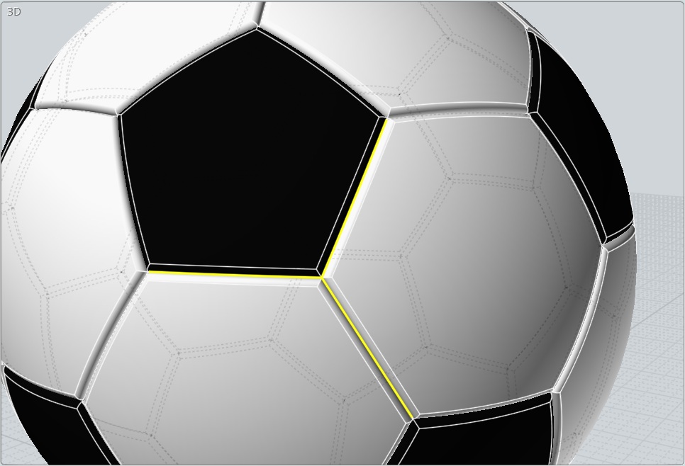
You must have your 2 diagonals selected!
script: /* Select by length */ var min = 9.7832259, max = 9.7832260; var crvs = moi.geometryDatabase.getObjects().getCurves(); for ( var i = 0; i < crvs.length; ++i ) { var crv = crvs.item(i); var len = crv.getLength(); if ( len>= min && len <= max ) { crv.selected = true; } }

I have just entered 2 diagonals....so only 2 diagonals will be selected!


with Vclone by maxSmirnov you can replace a "vector" by anything! :)
And each objects will take the same direction and size than the vector!
http://moi3d.com/forum/index.php?webtag=MOI&msg=6486.1

EDITED: 24 May 2021 by PILOU

  Reply Reply More Options
Post Options
Reply as PM Reply as PM
Print Print
Mark as unread Mark as unread
Relationship Relationship
IP Logged

Previous
Next
 From:  Psygorn (DRILLBIT)
10114.189 In reply to 10114.188 
Hi PILOU,

Thank you for your explanations :)

But I don't get it! Why u keep talking about diagonals?

I need to put stitches along these edges. Why should I look for diagonals?

  Reply Reply More Options
Post Options
Reply as PM Reply as PM
Print Print
Mark as unread Mark as unread
Relationship Relationship
IP Logged

Previous
Next
 From:  Frenchy Pilou (PILOU)
10114.190 In reply to 10114.189 
Because a diagonal will be considered like a vector by the Max Smirnov Vclone

Like this you will can replace anything you want by anything you want! :)

If you take the yellow edges how you will distinguish black faces and white face they have same length :)

but what is exactly your target ? Points for make what ?

the file that you give me has different surfaces sizes!

if You want make like the "photo"
with my method you have just to draw only 2 faces ( one black, on white)
Draw the vectors and launch the vClone (twice one for each color) ;)

EDITED: 24 May 2021 by PILOU

  Reply Reply More Options
Post Options
Reply as PM Reply as PM
Print Print
Mark as unread Mark as unread
Relationship Relationship
IP Logged

Previous
Next
 From:  Psygorn (DRILLBIT)
10114.191 In reply to 10114.190 
Hi PILOU,

if you take a look at the attached photo you will see a soccer ball and close to it there is a curve and 7 ring like objects ( I call these stitches)
Do you know a method with which I could replace all the shared edges between pentagonal faces and hexagonal ones with those stitches?

Take a close look at the black pentagonal face I have already put some stitches along one of its edges as an example so you could see what I mean!

  Reply Reply More Options
Post Options
Reply as PM Reply as PM
Print Print
Mark as unread Mark as unread
Relationship Relationship
IP Logged

Previous
Next
 From:  Frenchy Pilou (PILOU)
10114.192 In reply to 10114.191 
so many possibilities, Array files circular, vclone, Oriente Line/line (none) etc...
one method

orange tubes are stiches between Black & White faces
green tubes are stiches between white faces !

1 Black face top and 1 black face bottom
1 array circular from Top for 5 black faces, 1 array circular from bottom for 5 black faces

and only one circular for the last white faces with green tubes :)

EDITED: 24 May 2021 by PILOU

  Reply Reply More Options
Post Options
Reply as PM Reply as PM
Print Print
Mark as unread Mark as unread
Relationship Relationship
IP Logged
 

Reply to All Reply to All


Show messages:  1-12  …  113-132  133-152  153-172  173-192  193-212  213-232  233-252  …  633-637