Show messages:
1-20
21-33
From: ed (EDDYF)
Custom Truck Tutorial
Ed Ferguson, CascadiaDesignStudio.com
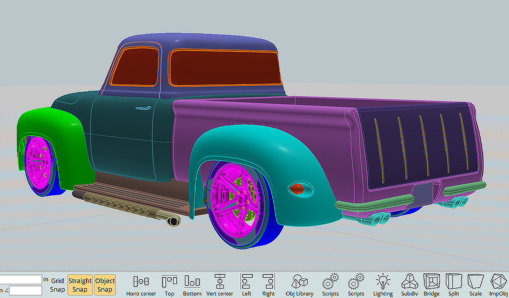
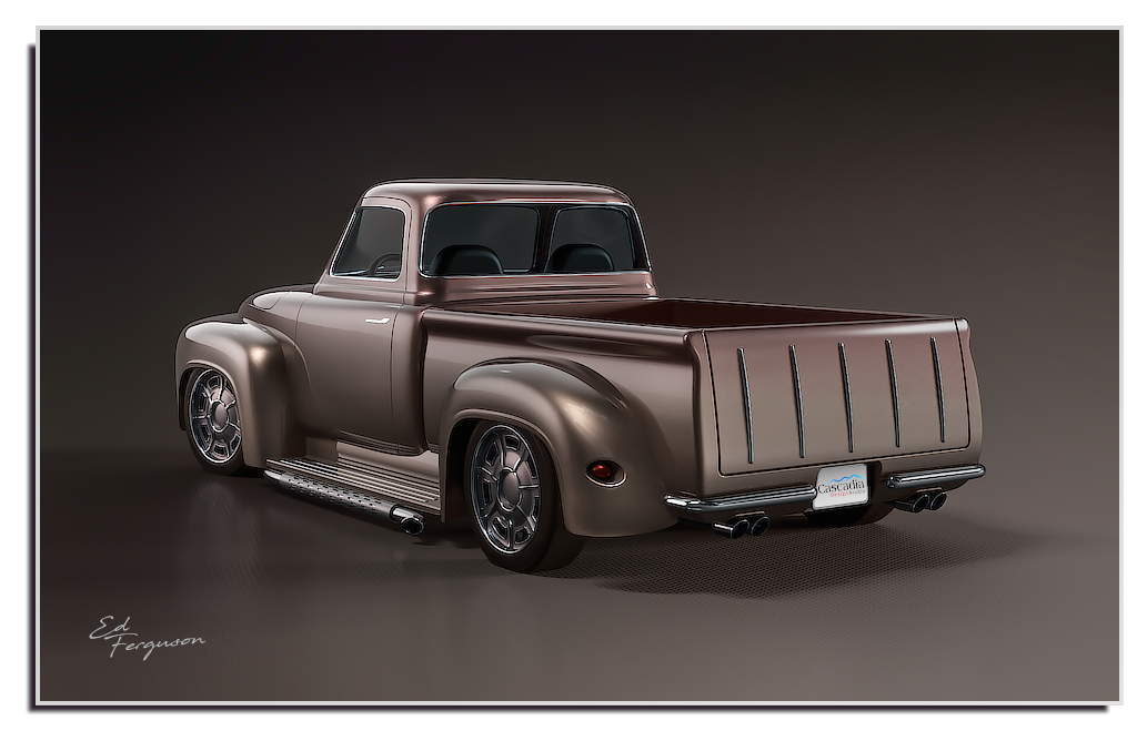
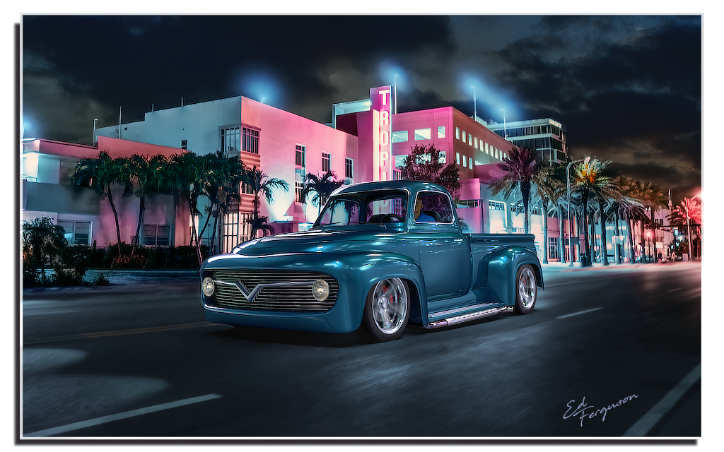
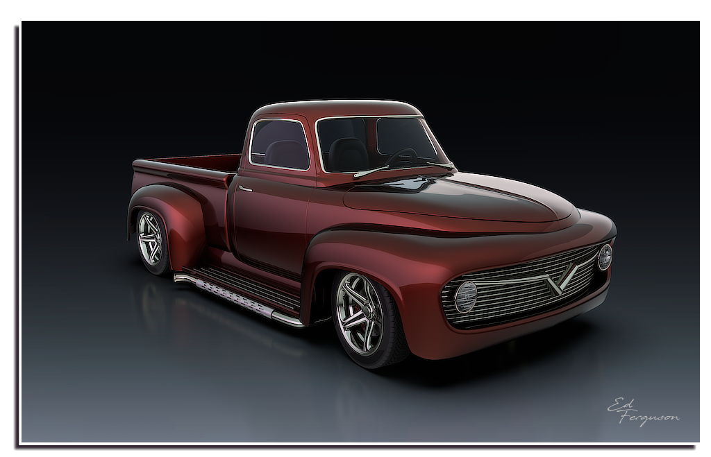
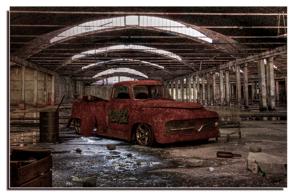
This model is a mix of different trucks from the 1950’s, integrating lines and features from Ford, Chevy and Studebaker. I integrated contours and features I liked from each truck and added some customizations like Camaro bumpers, Cadillac tail lights, Chevy Nomad tailgate bars and Tesla door handles. The result is the custom truck I’d love to build if I had the resources and skills.
Modeling this type of truck is easier than making a modern car because the body panels and fenders don't blend together. The upper & lower cab, bed, and fenders are modeled as distinct pieces without the need to patch and blend them together into a unified, smooth shape. For that reason I think this makes a good beginner's project.
From: ed (EDDYF)
Custom Truck Tutorial Part 1: Wheels
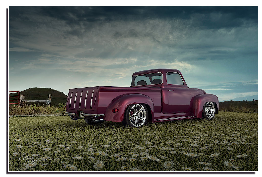
My truck renders show two styles of wheels: Spoke and Slotted. The spoked wheels are described in my 2015 tutorial here:
http://moi3d.com/forum/lmessages.php?webtag=MOI&msg=7389.4
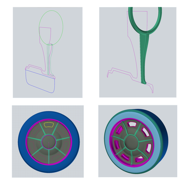
The slotted wheels begin with two profile curves representing the bottom half of the wheel: One for the rim (purple) and one for the tire (blue). Revolve the two profiles in unison around the wheel’s center line, into a full wheel.
Select the two spoke profiles (green) and Boolean Isect into a solid, then Fillet. Circular Array the spoke with count = 7. Sweep the green center circle with a 0.5” diameter circle to form the center ring.
Draw a closed curve for the slot at the 12 o’clock position and create an Offset to the inside, and another Offset to the outside. Delete the center curve. To produce the slot walls, select both curves and Extrude (Cap ends) about 2”. Select the outer cap surface and Fillet 0.1”.
Move the slot wall so it extends out of the rim by about 0.5”. Circular Array the slot wall with count = 7. Select all 7 slot walls and Boolean Diff with the wheel rim to produce 7 cutout slots.
From: ed (EDDYF)
Custom Truck Tutorial Part 2: Rear Fenders
Often with complex shapes built with NURBs you start by building a broader solid or surface, then Boolean or Trim sections off to arrive at the final shape. I was expecting to have to do this to make the fenders, but with this truck I was able to create the basic front and rear fenders in one operation using a Network.
The rear fenders are a Network of five curves. Using a side view photo of a truck taken off the Internet helps when drawing the curves. Once the overall shape was satisfactory, I modified the orange curve to form a small bump to make the wheel opening lip. Network: Lighter.
1959 Cadillac “bullet” tail lights are very popular on mid 50’s to early 60’s customized cars and trucks. To form the tail light tunnel, start with a 3.4” diameter cylinder and Boolean Union with the rear fender.
Next select the recessed cylinder & fender, and Join. Select the edge and Fillet 0.4” G1. Finally, draw a profile curve for the 6” long, 3” diameter bullet tail light lens and Revolve into a solid.

From: ed (EDDYF)
Custom Truck Tutorial Part 3: Front Fenders and Lower Hood
Construct the Network curves below to create the Front End in one go:
Network the eight curves: Network: Lighter. Note: The “Lighter” Network option gives an overall smoother result, at a slight loss of accuracy, due to fewer points being sampled on the input curves.
Once the overall shape was satisfactory, I modified the red curve to form two small bumps to make the lips around the wheel openings, and then performed the final Network operation.
In front view, draw a closed curve to represent the grill opening (Try to keep the point structure simple). Extrude (No Cap Ends) the curve into the Front End (but not out the back). Next, select the extrusion and the Front End, and then Boolean Merge. This results in a single cut out surface over the grill opening. Delete the extrusion as it is no longer needed.
Select the cutout surface resulting Merge and move it back 5”. Select the edges around the cutout, and Join to create a closed curve surrounding. Likewise, select the edges around the grill opening and Join to create a closed curve surrounding the opening. Select both curves and Loft Normal : Exact.
Select the Front End assembly, the lip, the back of the grill opening, and Join. The entire front end is now one joined surface.
Select the sharp edges at the front of the lip (made easier if you temporarily hide curves) and Fillet = 1” Circular. Finally I clicked on the grill back and assigned a different color so I can assign a unique material in my render program.
From: ed (EDDYF)
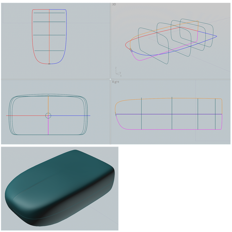
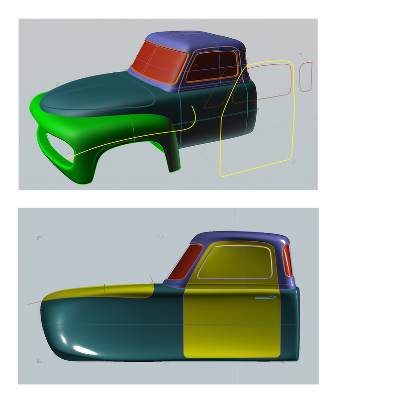
Custom Truck Tutorial Part 4: Lower Cab
The Lower Cab / Hood Assembly is a Network of 4 curves and 5 green profile closed curves. The 2nd green profile has a point at the top to form the hood crease. The circle at the front helps even out the structure where it converges. Network: Lighter.
From: ed (EDDYF)
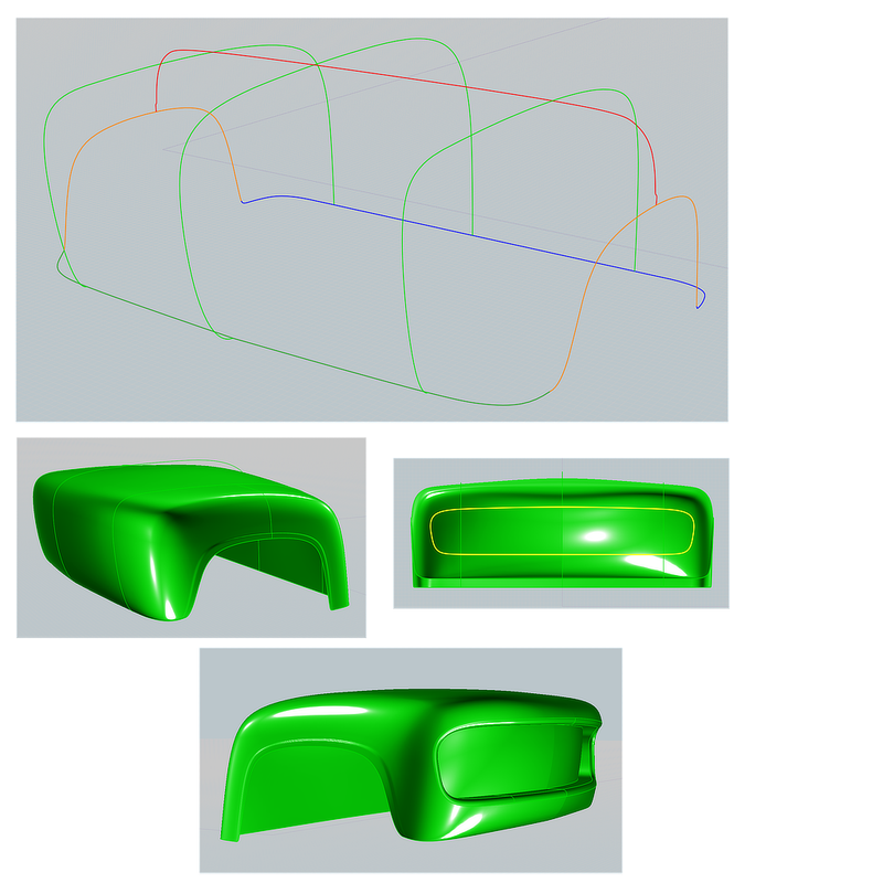
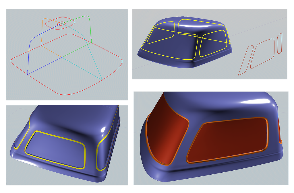
Custom Truck Tutorial Part 5: Upper Cab

The upper cab is a Network made of 7 curves.
The rounded red rectangle and circle at the top are not connected to the other curves, but their presence influences the network. The rectangle size and position influences the shape of the upper roof line (best to adjust when looking in top view). The circle helps to keep the network from bunching up when it converges at the center of the roof, resulting in a smoother surface. The effect of the rectangle & circle on the structure is easy to see if you select the completed network and Show Points.
Select all the network curves and Network: Mode: Normal This setting gave me the best result.
Next, draw 3 closed curves in side view to represent the window outlines.
Select the cab solid (Be sure the cab network curves are deselected). Perform a Trim and then select the 3 window curves as the cutting objects. Click Done. Select Mode: “Keep” with “Keep All Joined” checked. Click Done again. The cab should remain a solid after this step, and the windows are now individual Faces.
Note: In the prior step, do not select the cab and 3 window curves together, and Trim. That would produce a Mutual Trim, resulting in increased point density of the window profile curves. You’ll likely be adjusting the window profiles to finalize the design, so preserving the original point structure is important.
To Inset the windows, select the resulting window Faces (I had 5 faces because the rear window had a seam down the middle). Perform Offset > Inset 0.6” Inward. It may take a few moments to calculate and show results.
Troubleshooting: If a window fails to Inset, it’s probably because one or more window corner radii are too small, and/or the cab radii are too small. Edit the corners and try again). Also, any small kinks in the window curves can cause a fillet to fail to close, leaving a small sliver of a gap. Show points on the window curves and make sure all segments transition smoothly. Use the smallest number of points on a curve to get the job done.
Verify the cab remains a solid. If not, determine cause and fix it before continuing.
Select the flat “Frame” around each window (shown below in yellow) and Fillet 0.5” Circular to form the window chrome trim.
Select the window Faces and assign a unique color for assigning a glass material in the render program.
From: ed (EDDYF)
Custom Truck Tutorial Part 6: Truck Bed
Draw a rear profile curve and a side profile curve of the truck bed. Note that the rear profile curve has a straight line across the top, with two Corner Points. This ensures the top face of the bed is Planar which helps when making the fillets later. Boolean Isect the two curves and the result is a solid bed.
In Top View draw a rectangle to represent the bed cavity. Boolean Diff the rectangle with the bed. The result is a hole that goes completely through the bed.
Select the curved rear surface of the bed plus the flat front surface of the bed and Fillet 1.5” G3.
In Back View draw a closed curve that defines the tailgate opening. Extrude (Caps=No) the curve through the back wall of the bed and Boolean Diff with the bed. Delete the extrusion. The result is a solid bed and a solid tailgate.
Select the edges that make the upper, inside perimeter of the bed and tailgate opening. Fillet 0.3 circular. Select the entire tailgate solid and Fillet 0.3” Circular.
Draw a closed curve to represent the flared exhaust opening and mirror to the opposite side of the truck. Extrude the curves (w/ Cap Ends) just past the thickness of the tailgate, and then Boolean Diff with the bed.
Select the edges that make up the exhaust opening and Join to produce a single curve from those edges. In side view, draw an oval 0.5” x 0.4”. Sweep the oval using the exhaust channel curve as the Rail. This produces a solid, lip around the opening. Boolean Union the bed and the lip. Repeat for the opposite side of the bed. The bed remains a solid.
To make the five tailgate "Nomad Bars", copy the rear portion of the curve used to define the tailgate side view and trim it shorter. Draw a closed curve profile of the bar and Sweep it along the curve. Array five of the bars across the tailgate.
To create a recess for the license plate, draw a rectangle slightly larger than the license plate. Fillet the corners 1”, Extrude it forward to create a Solid, and Boolean Diff with the bed. Select the edges around the recess and Fillet 0.3” G3 Blend.

From: ed (EDDYF)
Custom Truck Tutorial Part 7: Hood & Door Seams
The hood and door seams are created using Boolean Merge followed by Fillets on the resulting edges.
In side view, draw a closed curve to represent the cab door opening. Draw an open curve to represent the hood opening.
Select the Upper and lower cab, and Boolean Merge with the two curves. The lower cab is now 3 solids and the upper cab is 2 solids.
Select the 3 lower cab solids and Fillet 0.14” Const Distance.
Select the door & door frame edges on the upper cab solids and Fillet 0.14” Const Distance.
That's almost everything. Finish by making some door handles, rear bumpers, exhaust pipes, running boards, front grill, and headlights.
Have fun!
From: aphaits
Really cool tutorial :D
Would love to see another one in a more modern style car!
edit: Really appreciated the article style tutorial that's getting rare in the internet. The quick pacing of youtube tutorials and the lack of clear concise descriptions sometimes makes learning hard. Not to mention also quality of audio.
From: Frenchy Pilou (PILOU)
Cool !
I put it in hurry on my Moi Site ...
...after your
https://moiscript.weebly.com/la-voiture-de-ed.html ;)
So let's start ;)
https://moiscript.weebly.com/le-truck-de-ed.html
From: corchet
excellent ! thanks for sharing !
From: Michael Gibson
It's really cool Ed, thanks for making the tutorial!
- Michael
From: danperk (SBEECH)
Very nicely done! Thanks Ed!
From: Mik (MIKULAS)
Excellent, these types of tutorials nicely represents the right thinking during the process of transformation from curves to solid/surface in MoI.
Thanks for sharing.
Mik
From: cad-guy
That was AWESOME! Thanks for sharing.
Message 9899.16 was deleted
From: Michael Gibson
(spam deleted)
From: Metin (METIN_SEVEN)
Very nice tutorial, Ed, many thanks for sharing.
I really need to use Network more often. It's quite powerful.
From: mrjynx
this is just what i was looking for. there are so many modern car modelling tutorials with the generic audi body shape that doesn't address the challenges of 50s car modelling.
tho in the 50s every year was unique.. now its almost like every years the same.
id love to see you do a 1959 cadillac
From: ed (EDDYF)
Thanks mrjynx - I hope the tutorial was useful.
As much as I like the 59 Caddy, modeling existing cars holds no interest for me. I prefer to blend features I like from several cars into a custom creation. That comes from growing up in Los Angeles in the 60's where every weekend, custom cars from miles around cruised the boulevard. It was like the movie American Graffiti on steroids.
Lately I've become interested in European cars from the 1930's. We called them "Big Fender Cars". They are true works of art.
Watch for a tutorial coming soon!
Ed Ferguson
Show messages:
1-20
21-33