Show messages:
1-9
10-29
30-49
50-69
70-72
From: BurrMan
Oh, thats just wrong.... (or is it right?)
From: Michael Gibson
Hi Burr,
> Something we dont/cant see.... Part of the underlying definition of the geometry.....
Yup, the parametrization comes from one of the pieces of data that makes up a NURBS curve - the "knot vector".
The data for the knot vector is just a list of increasing numbers like this for instance: 5, 6, 10, 20, 52
That knot vector there for example makes a curve that has a domain of 5 to 52 - that means that for every value between 5 and 52 the curve can be evaluated at that parameter value to produce a point location. That numeric range from 5 to 52 is the "parameter space" of the curve - a one-dimensional space that's part of the curve definition. Surfaces have 2 knot vectors, one for the U direction and one for the V direction and so they have a two dimensional parameter space.
The knot vector is not something you usually see directly because it would involve some huge spew of super techno-geek information that you would not particularly be able to do anything with.
But the knot vector comes into play in the overall mechanics of how the NURBS curve works - the relative spacing between different knots is one thing that affects how much influence the control points in that region of the curve have on the shape of the curve. Just to complicate matters there is also another totally separate type of data called "weights" that can also affect a control point's influence but the weights exist primarily because the particular type of influence they have is able to be leveraged to produce exact conic sections.
Being able to have different spacing between knot values is what gives the "NU" to NURBS, the NU stands for "Non-Uniform".
One of the main reasons why it is good to have this ability to do different knot spacings is to be able to more naturally set up interpolation through data points that deals better with the data points having some different spacing between them. When you try to interpolate an uneven distribution of points with a uniform spline (uniform means a knot vector with all equal spacing between all the knot values), it basically tries to produce the same length curve spans between each point and that makes for a sort of excess amount of curve being left over in areas where the points come closer together and that excess curve area makes for curly-cue type shapes in those areas.
The Rebuild command with the "fit to tolerance" method produces a curve that has a non-uniform knot spacing, but the spacing is based on the distances between the interpolated data points, so it matches the point spacing and makes the parameter space relate evenly to 3D space.
I've tried to make MoI set up in general so that you don't have to worry so much about these kinds of things, but it so happens that parametrization does come into play with surface-to-surface flow. I was able to make it not an issue in curve-to-curve flow since it is possible there to map distance traveled along each curve rather than just mapping parameter values from the base curve to the target curve. With a surface it's not so easy to do that since a surface can be warped and bulgy in multiple directions and have different distances across it in different areas.
And then to make things even more confusing, I guess it's even misleading when I wrote "evenly distributed parameterization" - to be more correct I guess it's more like "consistent distribution of parameter space as to 3D space".
- Michael
From: Mike K4ICY (MAJIKMIKE)
Michael, that was absolutely intriguing information. I had no clue it took so much to make a nice surface. (years of being stuck with four-point 2-D Brazier curves).
My PC at home is absolutely a giant lump of mud and it took two hours to do this version... man what a sad difference.
It worked!!! And it's even cleaner and more well groomed than the version using the arc-spacing points # method.
...interesting.... ;-) Chalk one up for Parameteorologicalivation!
From: Michael Gibson
Hi Mike, yup the "refit to tolerance" mode can tend to help resemble the original curve more accurately since it's adaptive and can add more detail just in bendy areas.
After you have done a rebuild like that, the result is all ready to go as far as eliminating parameter-space compression or stretching and it doesn't particularly matter how many control points are in the result.
So anyway, after all this I hope this explains why you it's not really needed to have an "unwrap to line with same control point structure" - instead of worrying about replicating the uneven spacing in your line it's far easier to just rebuild your bendy curve and then it's all ready at that point and will then match to a simple 2 point line segment just fine.
- Michael
From: BurrMan
Hi Michael,
Thanks for that explanation... I somewhat understood the original statement, but this explanation actually helps me in understanding some other stuff. In partucular, handeling data I read in with the opennurbs.dll. I would love to have big, long threads about it, though, I know that doesnt really fit into MoI's purpose or need.
Thanks again for taking the time with that response! Much appreciated.
Burr
From: Michael Gibson
Hi Burr, no problem!
Are you doing some kind of special project using OpenNURBS directly for your own program?
If you're stuck with dealing with 3DM data or understanding how some of the data is structured, you can open up a new thread with some questions in it if you like and I can try to at least point you in the right direction...
- Michael
From: BurrMan
Wow, thanks Michael,
At some point, I may take you up on that. Right now, I am just working on basics, that are just fundamentals I need to understand to undertake the task. I had an intent in doing some work with stuff to "add-on" to MoI.
""""""Are you doing some kind of special project using OpenNURBS directly for your own program?""""""""""
Yes. I'm working on reading 3dm data to my own viewport to interact with MoI, with minimal user managment...Like, at the moment, I can proceed with IGES, because I can read IGES, but that extra step kindof defeats the whole mission of MoI. So, I have a bit of work to do with just the simple 3dm studies, before I know what my questions are. (Also, alot of my goals became your goals, so I'm still on the fence)
I may find my goals to be a bit above my head, but if I get my head above ground, then some of the questions may be very helpful...
The offer is very valuable to me.... Thank you for that.
Burr
From: Michael Gibson
Hi Burr, do you mean one of your goals with your own 3DM reader was to do a curve length unwrapper like this one here? Do you have some other specific stuff that you are trying to get done?
- Michael
From: BurrMan
Hi Michael,
"""""""""do you mean one of your goals with your own 3DM reader was to do a curve length unwrapper like this one here?""""""""
No, totally unrelated... It was just a better understanding of what the underlying definition is.. Kindof like learning to read what I'm looking at when looking at the raw NURBS data. An analogy could be understanding how to write html with notepad instead of a wysiwyg editor. If I could write a 3dm file with notepad and then just compile it, I would be better at working with it!
From: Frenchy Pilou (PILOU)
This new function is also very cool for know the the length of curves ;)
From: Frenchy Pilou (PILOU)
Added :)
http://moiscript.weebly.com/unwrapcurve.html
From: bemfarmer
How about Style Color preservation for the UnwrapCurve?
From: Michael Gibson
Hi Brian,
> How about Style Color preservation for the UnwrapCurve?
I've updated the plug-in attached to the original post with a new version that should do that now, you can get it from here:
http://moi3d.com/forum/index.php?webtag=MOI&msg=5136.1
- Michael
From: bemfarmer
Thank you very much Michael!
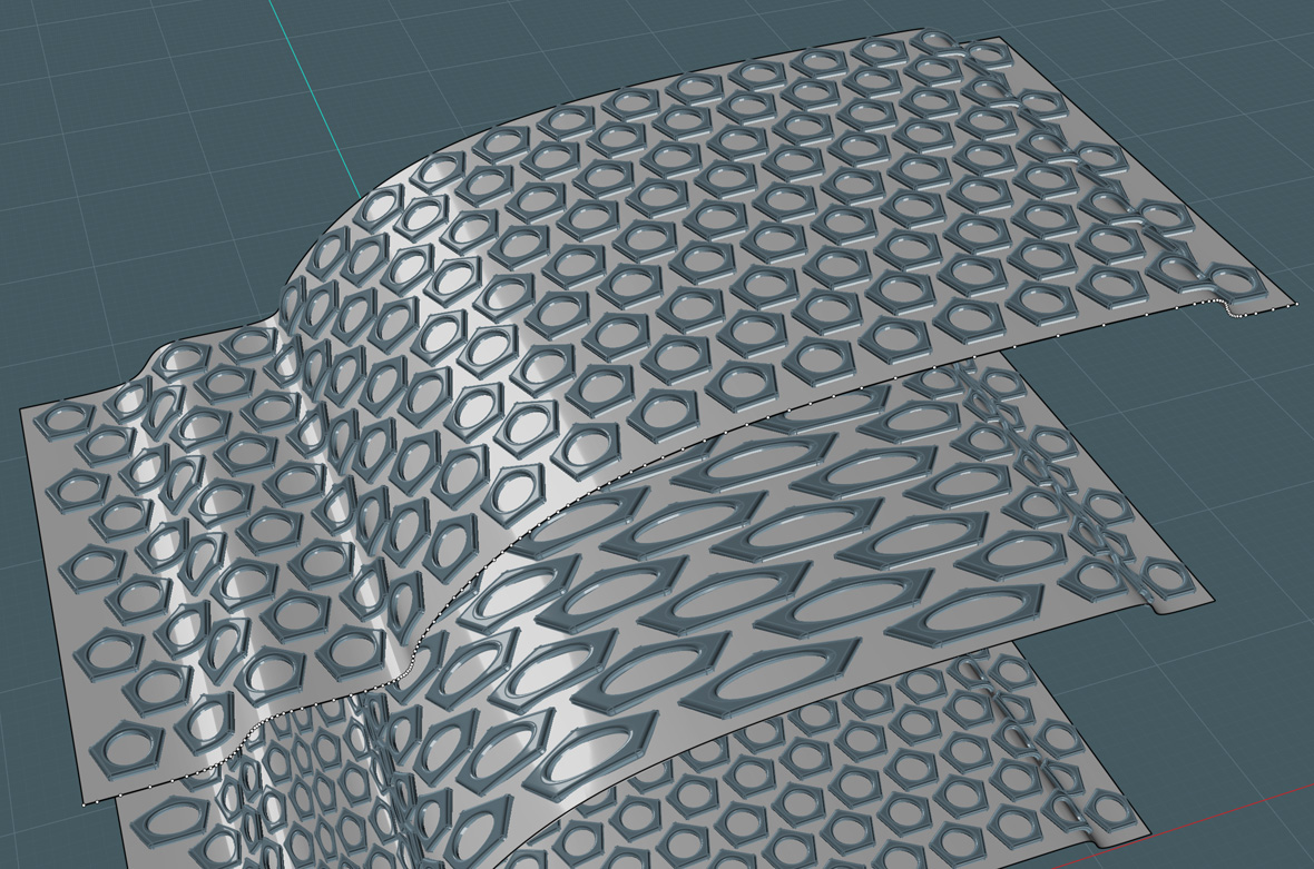
From: Stargazer
More examples :)
Unwrap Curve script + Curve to Curve flow

Rebuild +Unwrap Curve script + Surface to Surface flow


Image Attachments:
 Construction Lines 14.gif
Image101.jpg
Image97.jpg
Construction Lines 14.gif
Image101.jpg
Image97.jpg
From: Frenchy Pilou (PILOU)
Very cool pedagogic images!
From: Psygorn (DRILLBIT)
Hello, I was not able to achieve what you had achieved!
I used arc 3pts to create a curved surface then I used unwrap curve to create a flat surface ( I tried to keep the number of points equal using rebuild command)
Then I created a textured solid and finally used Flow command!) but I was not able to achieve what you had achieved!
Could you please help?
Attachments:
Curved_Texture.3dm
From: Michael Gibson
Hi Psygorn, if you select your surface and turn on control points, you should see that the "underlying surface" of your flat surface looks like this:

It's a rectangular plane with trim curves on it - that's the kind of surface that will be generated by the Construct > Planar command.
For use with Flow in your case here you need to construct a flat surface where the "underlying surface" has the trapezoidal shape to it, not just the trim curves having a trapezoidal shape. There are a few different ways to do that, one would be to loft between 2 lines like this:

If you then turn on surface control points for that shape, you can see that the actual surface has that trapezoidal shape to it, it's not just the trim curves that have that shape:

If you make the base surface like that, and also move it right on the bottom of the shape to deform, you can then run the Flow command on it to get this result (you can hide the object to be deformed after launching the Flow command to make it easier to pick on the base surface):

Let me know if you're still not able to produce this result.
- Michael
Image Attachments:
psygorn_flow1.jpg
psygorn_flow2.jpg
psygorn_flow3.jpg
psygorn_flow4.jpg
From: Psygorn (DRILLBIT)
Hi Michael,
I got the same results :) Thank you!
However, I noticed if the lines that are used to create the trapezoid surface using loft command have more points (let's say 10) The results would be different.
Edit: Also is it possible to unwrap cylindrical or curved surfaces directly?
From: Psygorn (DRILLBIT)
Update:
I had tried the same technique to create textured cylindrical shape, However the bumps end up inside of the cylindrical surface & not outside of it!
Note: I tried to click different corners of base surface and even rotated cylindrical surface along its height . I couldn't get desired result! what am I doing wrong?
Attachments:
Cylindrical_Texture.3dm
Show messages:
1-9
10-29
30-49
50-69
70-72