Show messages:
1-13
14-33
34-53
54-72
From: BurrMan
GHi Michael,
great explanation... I posted that before I saw your first response to Majik about that... My post was aimed at Majiks solution of building a revolve surface with the same point structure as the target, to use as a base for flow, But I think you answered that now... And also my question that just scaling doesnt produce the same "percentage spacing" as would need to be calculated for a proper points spacing.
Thanks for the time.
From: Mike K4ICY (MAJIKMIKE)
Thanks for the explanation Michael,
Before, when doing the revolve methods, I've had to create a spline "by eye" to get point spacing that was somewhat representative.
A case where I can think of where the need for this kind of spacing directed towards flow would be the design of art detail on the rounded surface of a ring.
Where you would want the art spaced on surfaces with concaved and curved elements. Or in a case where there are undulations in a surface that needs concise art to be flowed on it.
...but, there's generally an alternate solution to everything. ;-)
However, there have been many cases just in my adventures in the t-shirt and sign industry where having representative lines with exact and straightened information from curved sources is useful.
From: shayno
Here is an example that works for me, you can select an edge curve or 2 and run the script
This generates the two lines behind , that are the length of the edges laid out flat
You can then easily make the planar surface that is the correct length and width to match the target surface and use flow to wrap the text or other objects to the surface.
Brilliant

I made an even better example
Image Attachments:
 ScreenShot855.jpg
ScreenShot856.jpg
ScreenShot855.jpg
ScreenShot856.jpg
From: Michael Gibson
Hi Mike,
> Before, when doing the revolve methods, I've had to create a spline
> "by eye" to get point spacing that was somewhat representative.
Do you mean that you were altering the spacing to intentionally introduce uneven spacing and compression in some areas and squishing in other areas?
Or do you mean you were trying to eliminate that and have an even mapping from the base plane to the revolved surface?
Because if it's the latter and you wanted an even mapping, you could have achieved that by just drawing the revolve's profile curve any way that you like to start with, and then before revolving it do a Rebuild on it (with Refit to tolerance mode) - the result of the rebuild will be free of squishing or stretching in its parametrization and that will inherit to the revolved surface as well.
> However, there have been many cases just in my adventures in the t-shirt
> and sign industry where having representative lines with exact and
> straightened information from curved sources is useful.
Yup, and this plugin will do that.
I don't quite follow where the replication of the control point spacing onto the line would be helpful though. If you have a specific example file where that would be helpful could you please post it so that I could take a look at it?
- Michael
From: Michael Gibson
Hi Shayno, yup that's a great use of it to get the proper proportions of the flat plane of the same length as the circumference of your ring!
- Michael
From: Mike K4ICY (MAJIKMIKE)
I may try to create a better example later to show what I'm seeing in my head.
Here is an example of what I do to mimic the "straightened out" spacing of a more complex curve in order to flow something to it.
In the following pic, there are two curves. The top one is a curve with all kinds of bends and curvy stuff happening to it. - representative of my target flow surface.
The lower curve is one I made by hand with a spline tool. - straight, to use as the reference surface. I had to guess to approximate how far it was between each control point, as if I was able to stretch the top curve out straight.
The c-lines are just there to show the relationship between the original curve and it's control points to that of the straightened-out version.
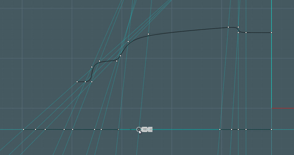
I used these curves to revolve them into circular surfaces, but it also works for a non-revolved flat surface if I simply extrude both of the lines to form rectangular surfaces.
Of course, just throwing control points along a straight line is not going to work accurately by eye, because the above control points of the shaped curves do not represent the true on-curve distance, they are used for spline control. But I can't think of any way to figure it out.
(man, is this an esoteric conundrum!)
From: Michael Gibson
Hi Mike, ok but what I have been trying to describe is that all you need to do is run Rebuild on that bendy curve and then after you have done that the rebuilt version of it has "arc length parameterization" - meaning that it will be a match to a simple single line as far as traveling along each in a uniform manner.
So if you want your revolve or extrude to have a "uniform traveling speed" matching property to a straight line, it's not necessary to construct such a complex multi-point straight line version of your curve like you are doing there, instead do a rebuild of your bendy curve before you construct your surface out of it and just have a simple regular line segment for the line.
Also note that none of this applies to curve-to-curve flow at all, it only deals with distance as traveled along the curve and so parameterization and control point spacing does not have any effect there.
Anyway, the key thing that I'm trying to explain is that yes - your bendy curve there that was drawn from Draw curve > Freeform > Control points has uneven parameterization as you currently show it. But if that uneven parameterization is going to cause a problem for you later on with surface-to-surface Flow then just run Rebuild on it (with "Refit to tolerance mode, not # of points mode), and the resulting rebuilt curve does not have uneven parameterization on it anymore. An even arc length parameterization is one of the properties of rebuild.
- Michael
From: Mike K4ICY (MAJIKMIKE)
> Hi Mike, ok but what I have been trying to describe is that all you need to do is run Rebuild on that bendy curve and then after you have done that the rebuilt version of it has "arc length parameterization" - meaning that it will be a match to a simple single line as far as traveling along each in a uniform manner.
Thanks Michael, that has awesome potential!
Let's take a look at how to implement this:
PREPARATION FOR FLOW BY USING REBUILD+
UNWRAPCURVE
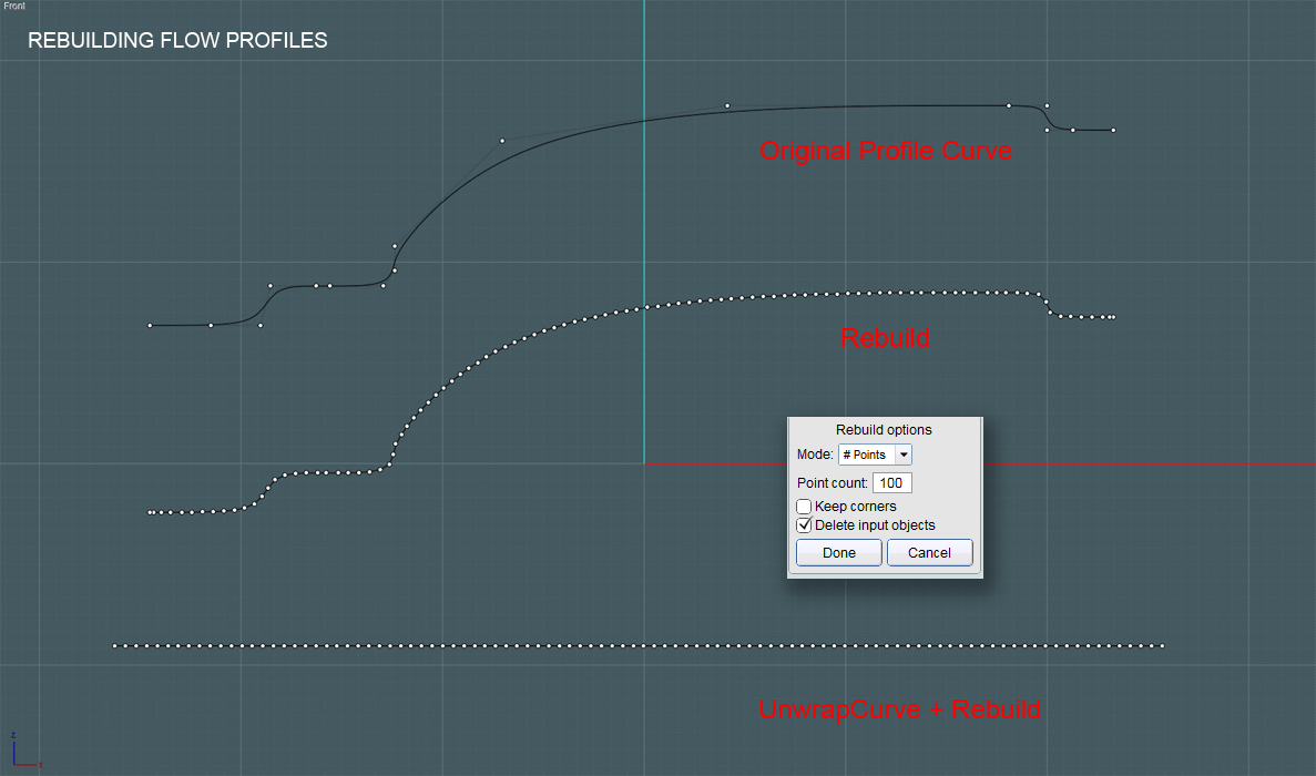
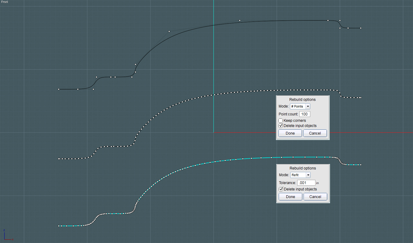
(looking at the pic)
The first curve at the top is the original spline representing the profile of our TARGET Flow surface.
The second curve in the middle was derived from the same profile curve using the Rebuild command. I chose 100# points, which as Michael pointed is used to build arcs or (near) even displacement along the curve's path.
The third line was derived from the profile curve using the new UnwrapCurve script.
It has also been rebuild (Rebuild) using 100# points, though it is still straight.
The advantage of using UnwrapCurve is to derive a line that is a close approximation of the true length of the profile curve when it is stretched out.
Therefore, when used as a Flow target, there shouldn't be too much overall length or dimensional distortion in the final result.
The goal is to make the original objects appear to flow along a surface naturally.
Now I'll use the profiles:
Note - You can also rebuild and unwrap curves (up to all four sides) to make a more complex Network.
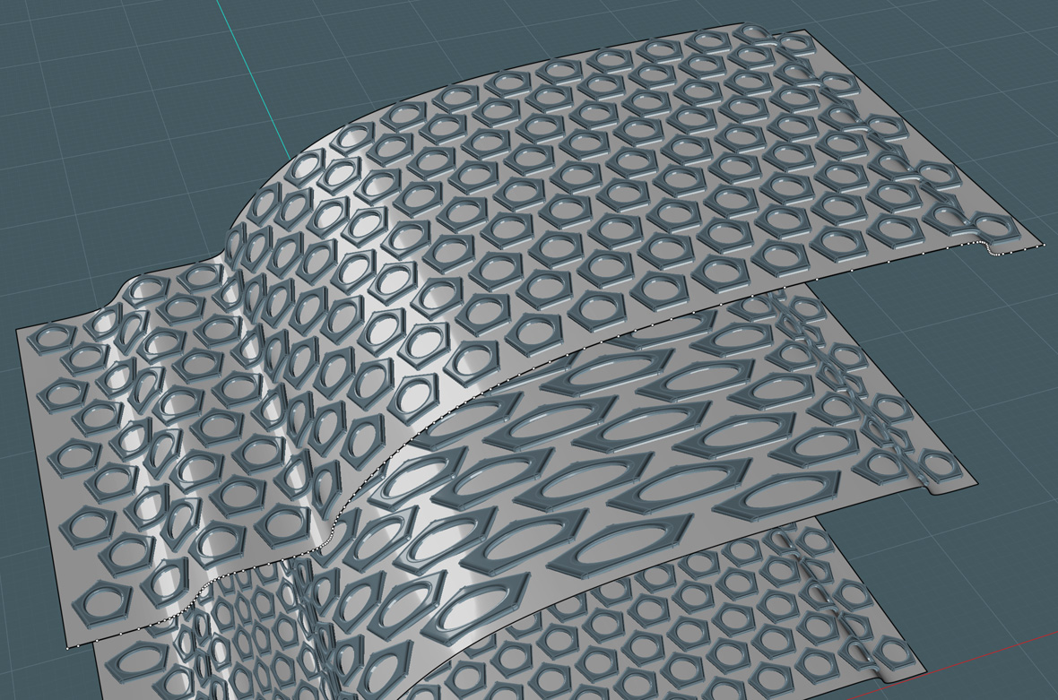
In this case, I Extrude the profiles and the line in order to create Target and Reference surface to try Flow with.
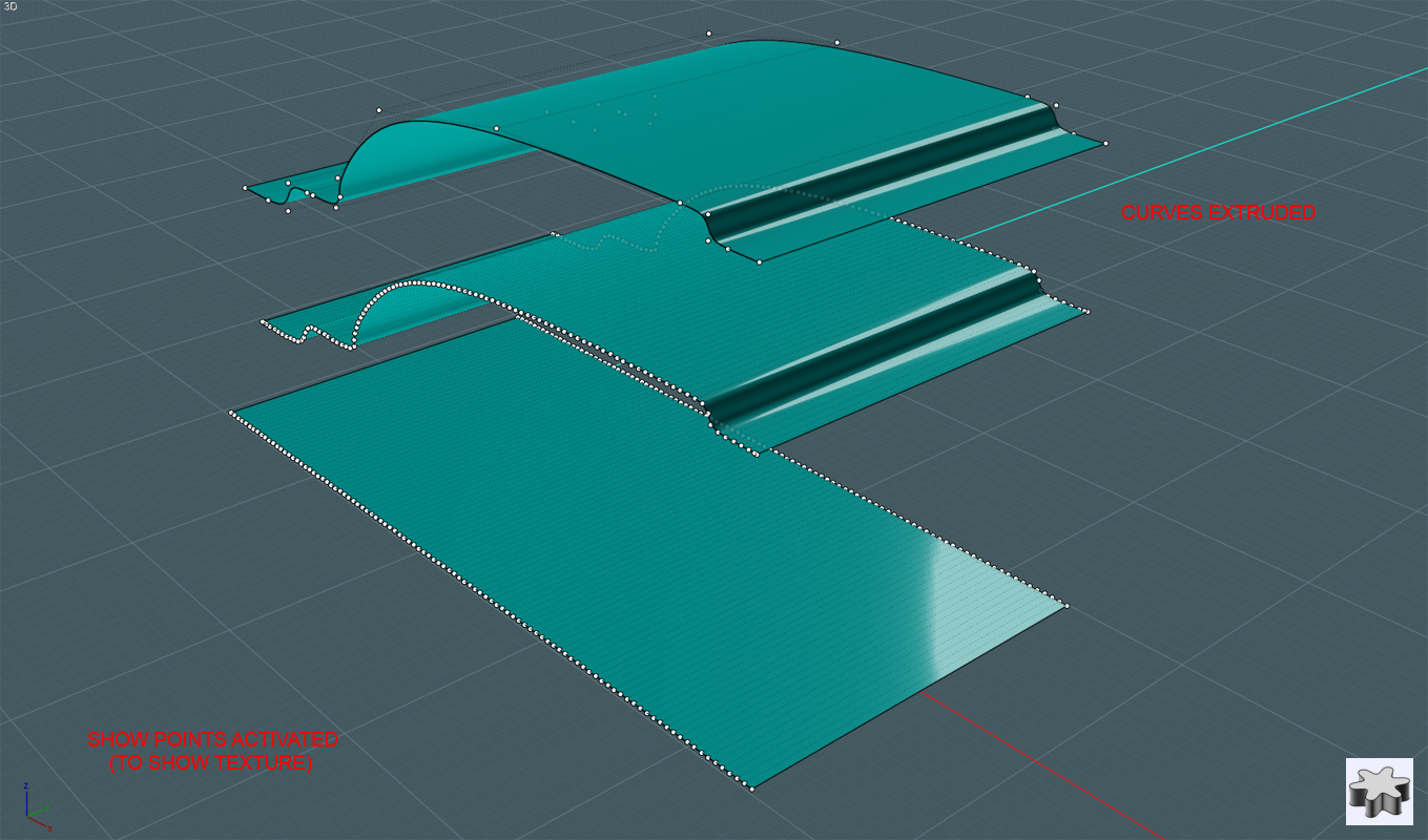
As you can see in this pic, the underlying points (isocurve) structures of these surfaces are constructed from the points within the profile curves.
These underlying arrangements will determine the the final placement of the flowed objects regardless of the appearance of the surfaces.
Here, I'll create a nice pattern to be flowed onto a surface created from my original profile:
I chose these pentagon/circle shapes to make a test pattern. Their shapes make it easy to see any relative distortion on the spatial arrangements when flowed.
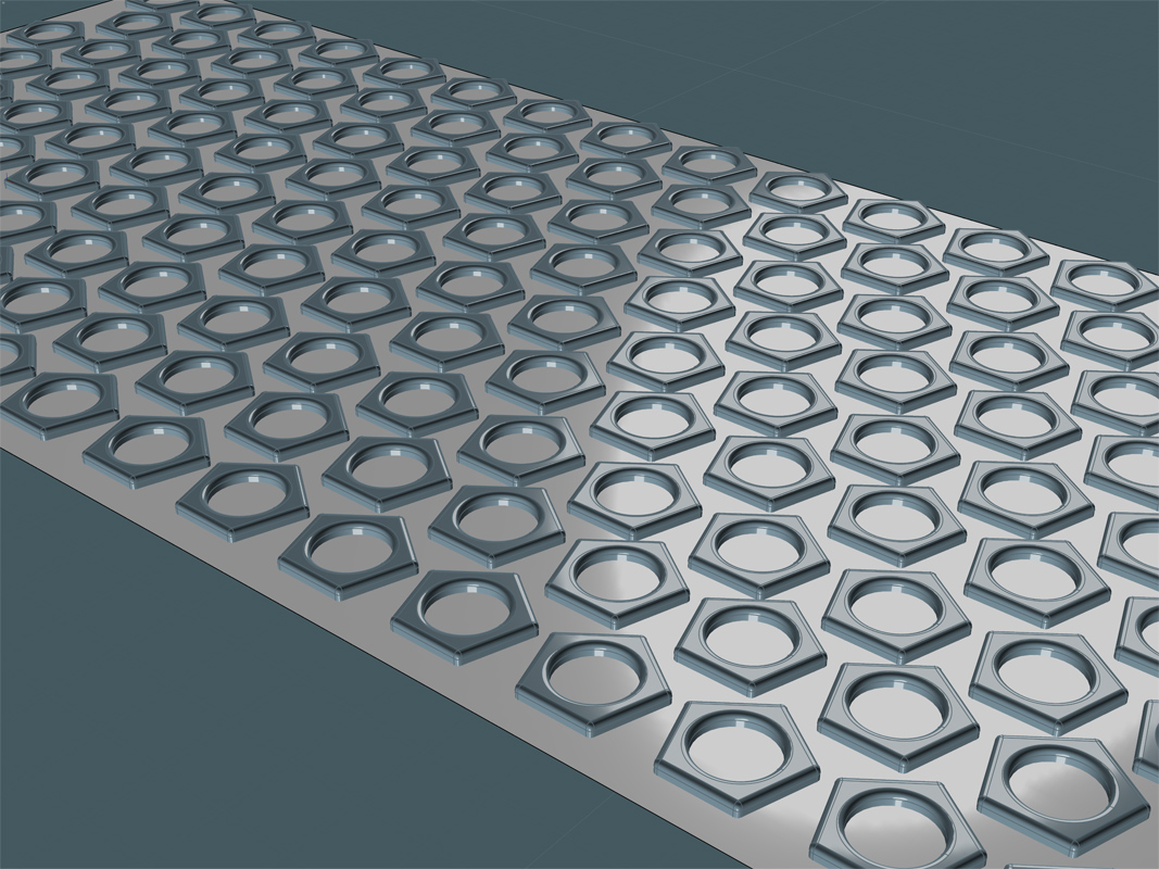
And here is the result!:
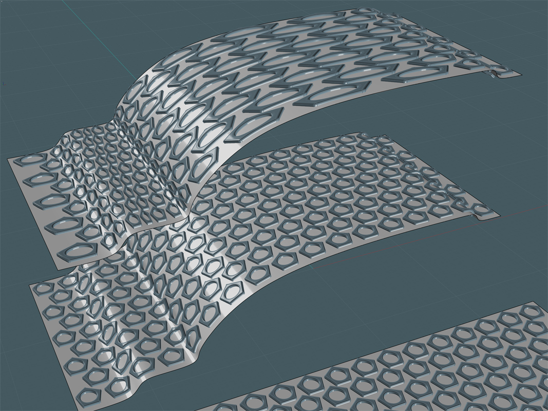
The Flow result on the top surface derived from the original profile curve has an awful displacement. (awful for what I needed in this instance) The distortions follow the "parameterization" of the control point arrangement in the original spline. This effect has advantages too and allows you to do neat things where this type of distortion is needed.
Ah! And you can see the Flow result in the middle. It has a very consistent-looking displacement.
For the Flow placement of shallow object arrangements, you can get very natural results this way.
Of course, the displacement of a flow is most accurate at the base surface level. As you move through the W (above and below) of the surface, distortion will occur due to the variances in the angular re-arrangements of the flowed objects. In other words, pinching and expanding will naturally occur.
I'm curious to try both a U and V arrangement.
From: ed (EDDYF)
Cool. I sense a new round of creativity is about to begin :)
Ed
From: Rich_Art
yeah,... lol...
Peace,
Rich_Art. ;-)
From: Mike K4ICY (MAJIKMIKE)
Oh the shear power and glory!
Michael throwing new scripts and features into the mix is like throwing fresh meat into a shark pool. ;-)
Oh yes... there is much potential here.
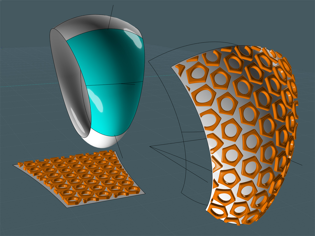
Though there is a little distortion along the middle, these Flowed objects placed quite well.
With this model I first made a ring shape by Sweeping a single arc around two bent circles.
I didn't use the surface created by the sweep, but I was able to project some lines to give me some accurate arcs.
All four boundary arcs were Rebuilt to 50# points. I made an extra one in the middle to help with making the Network.
So I made a 50x50 isocurve surface with Network for the side of this ring shape.
I used UnwrapCurve to make the four lengths needed for the planar reference surface.
I had to approximate the arc curve for the sides. Flattening one of the original arcs in an "ortho" direction helped make that.
I made sure to Rebuild the flat curves to the same number so that the two surface would jibe when Flowed.
A method like this means I have more control when Flowing art, type or patterns on something like a ring.
I didn't have to contend with squeezing or anything strange... I know some of you are itching to try this out!
Not that this could not be more easily achieved by guessing and going for a straight flow, but this works so well. ;-)
From: Michael Gibson
Hi Mike, those are great looking results!
You may want to use the "Refit to tolerance" mode for the rebuild though (try with a tolerance of 0.001), since that mode is able to add more detail to the rebuilt curve only in areas where it is more bendy, while at the same time giving a result that has an evenly distributed parametrization.
Also you should get the same results that you show with just leaving the line totally alone, you should not need to rebuild the line.
There is not any need to actually get the exact same number of control points in both the base and target curves - what you instead need is for each curve to have an evenly distributed parameterization which a line will already have without rebuilding it.
- Michael
From: Mike K4ICY (MAJIKMIKE)
Thanks for the pointers!
> You may want to use the "Refit to tolerance" mode for the rebuild though (try with a tolerance of 0.001)
Ehh... :-/ For some reason, that way ends up with unevenly distributed points.
From: Michael Gibson
Hi Mike,
> Ehh... :-/ For some reason, that way ends up with unevenly distributed points.
Yes it does, and it's supposed to - it adds more refinement in areas that are bendy.
But it also at the same time uses a knot vector spacing for the generated curve so that the parameterization matches that point spacing.
So the actual curve that is generated there has an even parameterization and will generate the same kind of "no stretching or squishing" result even though it has a non-uniform distribution of control points.
The key quality of the curve that you want to have is not actually "evenly distributed control points" - the thing you are looking for is actually "evenly distributed parameterization". The result of Rebuild with "refit to tolerance" mode will deliver that despite having non-uniform control point distribution.
- Michael
From: BurrMan
"evenly distributed parameterization".
Something we dont/cant see.... Part of the underlying definition of the geometry.....
From: Mike K4ICY (MAJIKMIKE)
Like how sausage is made.... ;-)
From: BurrMan
Oh, thats just wrong.... (or is it right?)
From: Michael Gibson
Hi Burr,
> Something we dont/cant see.... Part of the underlying definition of the geometry.....
Yup, the parametrization comes from one of the pieces of data that makes up a NURBS curve - the "knot vector".
The data for the knot vector is just a list of increasing numbers like this for instance: 5, 6, 10, 20, 52
That knot vector there for example makes a curve that has a domain of 5 to 52 - that means that for every value between 5 and 52 the curve can be evaluated at that parameter value to produce a point location. That numeric range from 5 to 52 is the "parameter space" of the curve - a one-dimensional space that's part of the curve definition. Surfaces have 2 knot vectors, one for the U direction and one for the V direction and so they have a two dimensional parameter space.
The knot vector is not something you usually see directly because it would involve some huge spew of super techno-geek information that you would not particularly be able to do anything with.
But the knot vector comes into play in the overall mechanics of how the NURBS curve works - the relative spacing between different knots is one thing that affects how much influence the control points in that region of the curve have on the shape of the curve. Just to complicate matters there is also another totally separate type of data called "weights" that can also affect a control point's influence but the weights exist primarily because the particular type of influence they have is able to be leveraged to produce exact conic sections.
Being able to have different spacing between knot values is what gives the "NU" to NURBS, the NU stands for "Non-Uniform".
One of the main reasons why it is good to have this ability to do different knot spacings is to be able to more naturally set up interpolation through data points that deals better with the data points having some different spacing between them. When you try to interpolate an uneven distribution of points with a uniform spline (uniform means a knot vector with all equal spacing between all the knot values), it basically tries to produce the same length curve spans between each point and that makes for a sort of excess amount of curve being left over in areas where the points come closer together and that excess curve area makes for curly-cue type shapes in those areas.
The Rebuild command with the "fit to tolerance" method produces a curve that has a non-uniform knot spacing, but the spacing is based on the distances between the interpolated data points, so it matches the point spacing and makes the parameter space relate evenly to 3D space.
I've tried to make MoI set up in general so that you don't have to worry so much about these kinds of things, but it so happens that parametrization does come into play with surface-to-surface flow. I was able to make it not an issue in curve-to-curve flow since it is possible there to map distance traveled along each curve rather than just mapping parameter values from the base curve to the target curve. With a surface it's not so easy to do that since a surface can be warped and bulgy in multiple directions and have different distances across it in different areas.
And then to make things even more confusing, I guess it's even misleading when I wrote "evenly distributed parameterization" - to be more correct I guess it's more like "consistent distribution of parameter space as to 3D space".
- Michael
From: Mike K4ICY (MAJIKMIKE)
Michael, that was absolutely intriguing information. I had no clue it took so much to make a nice surface. (years of being stuck with four-point 2-D Brazier curves).
My PC at home is absolutely a giant lump of mud and it took two hours to do this version... man what a sad difference.
It worked!!! And it's even cleaner and more well groomed than the version using the arc-spacing points # method.
...interesting.... ;-) Chalk one up for Parameteorologicalivation!
From: Michael Gibson
Hi Mike, yup the "refit to tolerance" mode can tend to help resemble the original curve more accurately since it's adaptive and can add more detail just in bendy areas.
After you have done a rebuild like that, the result is all ready to go as far as eliminating parameter-space compression or stretching and it doesn't particularly matter how many control points are in the result.
So anyway, after all this I hope this explains why you it's not really needed to have an "unwrap to line with same control point structure" - instead of worrying about replicating the uneven spacing in your line it's far easier to just rebuild your bendy curve and then it's all ready at that point and will then match to a simple 2 point line segment just fine.
- Michael
Show messages:
1-13
14-33
34-53
54-72