Show messages:
1-20
21-40
41-60
61-71
From: Michael Gibson
I cooked this up to help someone through e-mail and thought it might be useful to others.
The attached UnwrapCurve plug-in will generate flattened lines from input curves, with the line having the same length as the full length of the curve.
It places the lines onto the x/y plane, with the midpoint of the line at the midpoint between the projection of the curve's endpoints, and the direction of the line as the direction between the curve's endpoints. If the curve is closed (and so the start/end are on the same point and not forming a unique direction as with an open curve), it just uses the x-axis as the direction for the line.
So it makes things like this, with input like this:

It will produce these lines:

The lines there are not a planar projection of the curves, the lines are of the same length as the length of each curve, so they stick out to the sides more than a planar projection would.
You can also use it on a circle to easily spit out a line that is the same length as the perimeter of the circle.
To set it up, unzip the attachment and copy the 2 files into MoI's commands folder - in Windows you can find this as a sub-folder inside of MoI's main installation folder inside of \Program Files, and under OSX right-click on the MoI .app and choose "Show package contents", and then inside there go to drive_c/moi/commands.
After you have copied the 2 files into MoI's commands folder that will then make a new UnwrapCurve command available to MoI and you can set up a shortcut key with that as the command name to launch it, or you can push Tab and type in UnwrapCurve and push enter as an alternate way to launch it.
Hope it may be useful!
- Michael
EDIT: 6/1/2012 - updated unwrap curve to preserve object properties such as style on the generated lines.
EDIT: 7/29/2023 - updated unwrap curve to place line on current cplane z = 0 instead of only world z=0.
Attachments:
 UnwrapCurve.zip
Image Attachments:
unwrap_curve1.jpg
unwrap_curve2.jpg
From: BurrMan
Thanks Michael,
I've been using the curve length script and notepad for awhile Now. This will be speedy!!!
From: Mike K4ICY (MAJIKMIKE)
Mother of pearl! I've wanted this ability for 20 years using Corel.
It has the occasional usefulness, especially with sign-making and other real-world need-to-knows, when the true length of something curved is important.
All I gotta do is import whatever I need to measure from Corel as an .ai.
Thanks Michael!

From: Michael T. (MICTU_UTCIM)
Thanks Michael G. I've been doing the same as Burrman. Can't wait to try this!
Michael T.
From: Rich_Art
Cool. No idea where to use it for but it is a great option to have. :-)
Peace,
Rich_Art. ;-)
From: BurrMan
Hey Rich_Art,
"""""""""""""Cool. No idea where to use it for but it is a great option to have.""""""""""
There are a few places where someone may want it, but as a base, it will be good for "flow". If you are trying to match thins up using flow, it is best to have the origin/target curves/surfaces be the same size. Coupled with the same "Point structure", things should match up pretty well... So if you are going to flow to a curvy target, the originating curve should be the same length. FYI.
From: Michael Gibson
Hi Burr, just a quick note on this part:
> Coupled with the same "Point structure", things should match up pretty well...
For curve-to-curve Flow it shouldn't matter if the base curve and the target curve have the same number of control points in them or not. It works by measuring distances traveled along each curve and so it just follows the curve's shape and isn't sensitive to anything specific about each one's control point structure.
Surface-to-surface Flow is a somewhat different story, where the "parameterization" of the surfaces do come into play, so those can be affected not so much by just control point counts, but whether the control points are evenly distributed or bunched together or stretched apart in different areas, the flowed result will follow that type of bunching or stretching.
- Michael
From: Mike K4ICY (MAJIKMIKE)
> Surface-to-surface Flow is a somewhat different story, where the "parameterization" of the surfaces do come into play, so those can be affected not so much by just control point counts,
Michael, I did want to ask you about that:
Is it possible to add an option where the new line (curve) could be made with control points matching the original curve, but straightened out?
Of course, the only purpose the control points would serve is to match "parameterization" when extruding this line to make a reference surface for flow.
You may have seen where I've taken this into account when I perform a "flow on revolved surface".
I dunno, just a thought.
From: Michael Gibson
Hi Mike,
> Is it possible to add an option where the new line (curve) could be made
> with control points matching the original curve, but straightened out?
The control point structure of the curves are not accessible to scripts right now, so I don't think there is any way to do that currently. More stuff needs to be added to the script interface to make that possible.
- Michael
From: Michael Gibson
Hi Mike, but also if you do a Rebuild of the curve the rebuilt version of the curve will have an "arc length" parameterization where the parameterization of the curve is based on distance and so has the same parameterization as a line anyway.
So just do a Rebuild (with the Refit to tolerance mode) on the starting curve if you see any uneven squishing in the surface-to-surface flow results and it should solve that problem - constructing a line with the same control point count should not be required.
The rebuilt curve will have an arc length parameterization even if you see unequally spaced control points on it, since the control point spacing and parameterization of knot values are synchronized in that case.
This is the main reason why several surfacing commands like Loft and Network, etc.. incorporate a rebuild step on the profile curves as part of the surfacing process, so that the surface generated will spread out evenly based on distance traveled along the curves rather than bunching up where parameter space is compressed or stretched.
It's not actually uneven control points all by itself that causes uneven parameterization, that's just a bit of a simplified explanation - you get uneven parameterization when the parameter values between knots are stepping at some kind of constant rate like just a value of 1 between each knot value while meanwhile the control points are stepping at some other distances than that. You do get a curve like that if you draw a control point curve and have unequal spacing in the control points that you placed though - a control point curve from Draw curve > control points has a uniform knot vector.
- Michael
From: BurrMan
"""""""""Is it possible to add an option where the new line (curve) could be made with control points matching the original curve, but straightened out?""""""""""
So with this in mind, I copied and pasted the original points, then used BoundingBox and centered the points on the new "unwrapped" line. Used the scaling widget to flatten them down to the line.
I suppose the question though, would be:
"I used scale from center", to bring the point stucture into length with the new line... Does that distribute them "Properly"? or is it just close. Would a "stretch" be different? Like distorting it more?

From: Michael Gibson
Hi Burr,
> "I used scale from center", to bring the point stucture into length with
> the new line... Does that distribute them "Properly"? or is it just close.
> Would a "stretch" be different? Like distorting it more?
The problem is that it's not only the control point spacing that controls the parameterization of a curve (or of a U or V direction in a surface) - part of the information that makes up a curve is also a knot vector which also controls how the parameter space of a curve is formed.
That kind of control point spacing that you show there would be correct if the original curve had a uniform knot vector, but not if it had a non-uniform knot vector, if it had a non-uniform knot vector that knot vector would also need to be used in your new curve as well.
When you draw a new control point curve, it gets a uniform knot vector, one with even spacing between the knots.
You could solve what you show there by reconstructing the surface to have arc-length parameterization, that will then make it have a distance-based parameterization and so it will behave the same as a line, then you do not need to try to recreate any control point spacing.
You would reconstruct that extruded surface to have arc length parametrization in its bendy direction by extracting out the profile curve, running Rebuild on it with the refit to tolerance mode, and then re-extruding the rebuilt curve back out again.
But often if you're just using an extruded surface in surface-to-surface flow you can just get the same result by using curve-to-curve flow instead and like I mentioned previously curve-to-curve flow is itself based off of distance traveled along each curve and so it not sensitive to parameterization at all.
Do you have some flow example that you could show where you think you need to recreate that control point spacing? I can then show you how to avoid the need for it - the answer will be though to either use Rebuild on your curve before constructing a surface out of it or to use curve-to-curve flow instead of surface-to-surface flow.
- Michael
From: Michael Gibson
Hi Burr, and now that I see that you just squished the control points down by scaling - no that's not how you would maintain the proper spacing in any case, you would need to measure the distance along the entire control polygon and then measure the percentage distance of each particular point along that polyline, and that percentage is where you would place it on the line. But like I mentioned before that would only work if the knot vector on the original curve is a uniform knot vector.
It should not be necessary to do any of that at all though, either doing Rebuild or doing curve-to-curve flow would avoid any issues with uneven parametrization.
- Michael
From: BurrMan
GHi Michael,
great explanation... I posted that before I saw your first response to Majik about that... My post was aimed at Majiks solution of building a revolve surface with the same point structure as the target, to use as a base for flow, But I think you answered that now... And also my question that just scaling doesnt produce the same "percentage spacing" as would need to be calculated for a proper points spacing.
Thanks for the time.
From: Mike K4ICY (MAJIKMIKE)
Thanks for the explanation Michael,
Before, when doing the revolve methods, I've had to create a spline "by eye" to get point spacing that was somewhat representative.
A case where I can think of where the need for this kind of spacing directed towards flow would be the design of art detail on the rounded surface of a ring.
Where you would want the art spaced on surfaces with concaved and curved elements. Or in a case where there are undulations in a surface that needs concise art to be flowed on it.
...but, there's generally an alternate solution to everything. ;-)
However, there have been many cases just in my adventures in the t-shirt and sign industry where having representative lines with exact and straightened information from curved sources is useful.
From: shayno
Here is an example that works for me, you can select an edge curve or 2 and run the script
This generates the two lines behind , that are the length of the edges laid out flat
You can then easily make the planar surface that is the correct length and width to match the target surface and use flow to wrap the text or other objects to the surface.
Brilliant

I made an even better example
Image Attachments:
ScreenShot855.jpg
ScreenShot856.jpg
From: Michael Gibson
Hi Mike,
> Before, when doing the revolve methods, I've had to create a spline
> "by eye" to get point spacing that was somewhat representative.
Do you mean that you were altering the spacing to intentionally introduce uneven spacing and compression in some areas and squishing in other areas?
Or do you mean you were trying to eliminate that and have an even mapping from the base plane to the revolved surface?
Because if it's the latter and you wanted an even mapping, you could have achieved that by just drawing the revolve's profile curve any way that you like to start with, and then before revolving it do a Rebuild on it (with Refit to tolerance mode) - the result of the rebuild will be free of squishing or stretching in its parametrization and that will inherit to the revolved surface as well.
> However, there have been many cases just in my adventures in the t-shirt
> and sign industry where having representative lines with exact and
> straightened information from curved sources is useful.
Yup, and this plugin will do that.
I don't quite follow where the replication of the control point spacing onto the line would be helpful though. If you have a specific example file where that would be helpful could you please post it so that I could take a look at it?
- Michael
From: Michael Gibson
Hi Shayno, yup that's a great use of it to get the proper proportions of the flat plane of the same length as the circumference of your ring!
- Michael
From: Mike K4ICY (MAJIKMIKE)
I may try to create a better example later to show what I'm seeing in my head.
Here is an example of what I do to mimic the "straightened out" spacing of a more complex curve in order to flow something to it.
In the following pic, there are two curves. The top one is a curve with all kinds of bends and curvy stuff happening to it. - representative of my target flow surface.
The lower curve is one I made by hand with a spline tool. - straight, to use as the reference surface. I had to guess to approximate how far it was between each control point, as if I was able to stretch the top curve out straight.
The c-lines are just there to show the relationship between the original curve and it's control points to that of the straightened-out version.
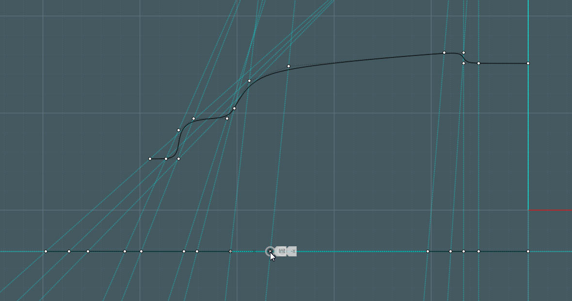
I used these curves to revolve them into circular surfaces, but it also works for a non-revolved flat surface if I simply extrude both of the lines to form rectangular surfaces.
Of course, just throwing control points along a straight line is not going to work accurately by eye, because the above control points of the shaped curves do not represent the true on-curve distance, they are used for spline control. But I can't think of any way to figure it out.
(man, is this an esoteric conundrum!)
From: Michael Gibson
Hi Mike, ok but what I have been trying to describe is that all you need to do is run Rebuild on that bendy curve and then after you have done that the rebuilt version of it has "arc length parameterization" - meaning that it will be a match to a simple single line as far as traveling along each in a uniform manner.
So if you want your revolve or extrude to have a "uniform traveling speed" matching property to a straight line, it's not necessary to construct such a complex multi-point straight line version of your curve like you are doing there, instead do a rebuild of your bendy curve before you construct your surface out of it and just have a simple regular line segment for the line.
Also note that none of this applies to curve-to-curve flow at all, it only deals with distance as traveled along the curve and so parameterization and control point spacing does not have any effect there.
Anyway, the key thing that I'm trying to explain is that yes - your bendy curve there that was drawn from Draw curve > Freeform > Control points has uneven parameterization as you currently show it. But if that uneven parameterization is going to cause a problem for you later on with surface-to-surface Flow then just run Rebuild on it (with "Refit to tolerance mode, not # of points mode), and the resulting rebuilt curve does not have uneven parameterization on it anymore. An even arc length parameterization is one of the properties of rebuild.
- Michael
Show messages:
1-20
21-40
41-60
61-71