Show messages:
1-18
…
299-318
319-338
339-358
359-378
379-398
399-418
419-438
…
1859
Thread Split: Some posts in this thread have been moved here
From: Frenchy Pilou (PILOU)
<< Or do you think that we have to have a line web node?
Will be perfect because it's a tricky thing for make easily some regulate surfaces!
From: Karsten (KMRQUS)
Hhhmm!
That's all!?!

Image Attachments:
 LineWeb.png
From: Frenchy Pilou (PILOU)
I will try that! :)
Just about indepth of the beast of a node...(just by curiosity because i will never code that)
You must re-create all the function or you recall an existing function (here Line Web) somewhere ?
Else for a Node Line Web itself
- Nbs point by curves
- Nbs of curves
- Variation of curves (distort curves)
another infinite variations! :)
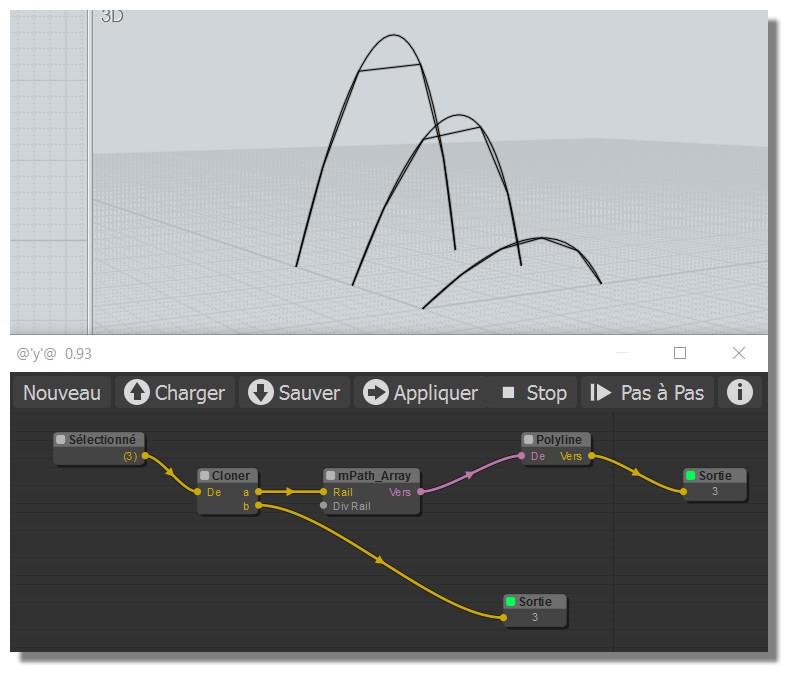
Ps Can you post your node because I don't obtain the same! :(
(or maybe i don't make the good process ?
http://moiscript.weebly.com/uploads/3/9/3/8/3938813/line_web.nod
From: speedy (AL2000)
Hello Pilou
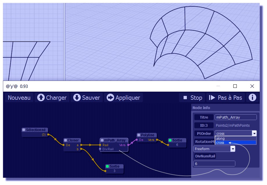
You have to set-up "cross " in the node preferences,
(mpath array )
al
From: Frenchy Pilou (PILOU)
@Al
Ahhh yes! Some indispensable hidden things! Bravo!
(Now Lineweb native is more simple! ;)
But as soon as more nodes will added that will be rocking!
Maybe the Info window must be open as soon has a new node is created!
From: Frenchy Pilou (PILOU)
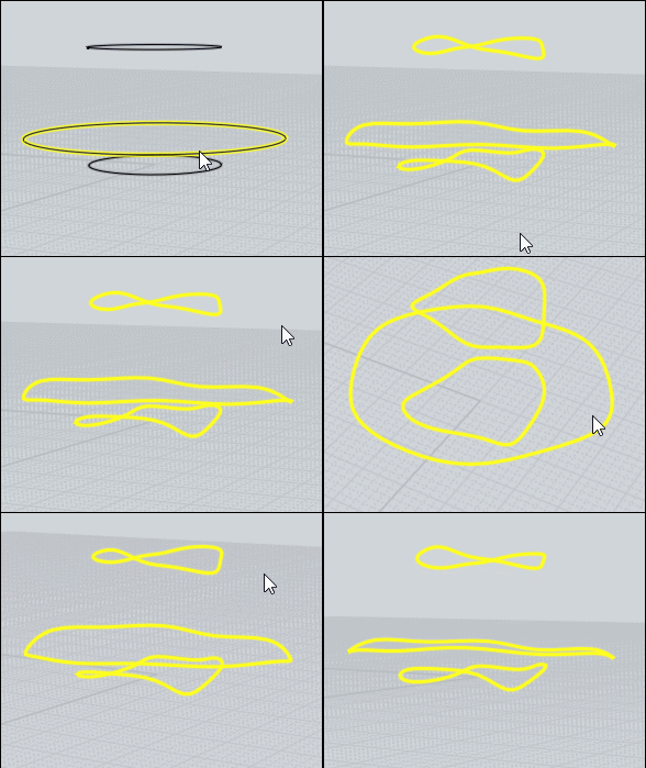
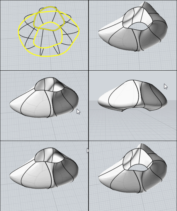
Distort ? By Max Smirnov
http://moi3d.com/forum/index.php?webtag=MOI&msg=6659.13
For crazy vegetables! :)
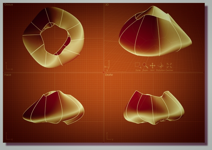
From: speedy (AL2000)
Hello Friends
an experimental test of a sphere tasselation
with base Icosahedron
link:http://www.mediafire.com/file/3h0nk02r0u11hhl/Geodesic_Tasselation.rar
Have a nice day to all
al
From: James (JFH)
Al et al,
I have had no opportunity to play with node editor for the last couple of months,
but this weekend I teased apart your Spir-Curve nod to comprehend your method.
After researching roulette curves, I started from scratch to produce this very simple scheme (no trig) based on your method for Trochoid curves.
It can also create Epicycloids by flipping the vectors
(i.e. multiplying by -1 bottom most node)
Now I am going to try and get my head around your geodesic nod.
It looks amazing!
Have a great weekend
James
Image Attachments:
 Trochoid.jpg
From: Barry-H
Hi,
I'm running an animation with the node editor and was wanting to hide edges.
I've tried hiding them prior to running the animation but this does not work.
Is it possible to have a node to hide them ?
Barry
From: bemfarmer
Hi Barry.
The code which loads the .3dm object is located here:
Under Node/Objects/Get by name
Perhaps a line could be added there. I do not know how:-(
The following code did not work:
// TEST edge hidden code (BAD)
this.inputobjects.edges.setProperty('hidden', true);
// End Test Code
- Brian
From: Barry-H
Hi,
I have been able to produce animations of the bottle feed screw with a constant pitch helix
and also a variable pitch helix but I would like to be able to produce a screw that as a mixture of both
i.e: start constant pitch then variable pitch exit constant pitch.
So my total movement is X = A + B + C
If I have a slider for X how can I switch to the various move profiles without have separate sliders ?
Any ideas .
Barry
From: speedy (AL2000)
Hello James
welcome back
I like to feel you.....
Well done , Trochoid .nod , turns out
Clear and Nice definition
Good Work my friend
al
From: bemfarmer
Hi Barry,
Some math would seem to be in order.
The screw turns with constant RPM, but the horizontal velocity of the bottle in mm/cm/meters per second, varies between constant sections, and variable section.
The horizontal velocity in the variable section also is not constant. (?)
The constant sections have constant horizontal velocity.
There are formulas to convert Pitch to Lead.
So the horizontal range must be split up into different velocities with some Logic.
Say the fastest constant section uses the straight clock.
When in a slower constant section, the bottle speed, or clock, will have to be adjusted down.
When the bottle is in the variable section, Multiply or divide the variable sections clock by the conversion equation(s).
The original litegraph had a bunch of functions...
- Brian
From: Barry-H
Hi Brian,
I'm using the maths you supplied with the variable pitch helix script.
I.e, the z axis and that works great.
For the constant pitch that was based on distance and number of coils
Or degrees of revolution.
I'm trying to have a slider or quartz widget that is the the full movement
but at various points it toggles to next profile maths function.
As an example say 20cm constant next 60 cm variable and finally 20cm constant.
Being able to toggle between profile functions allows different permutations.
I could do it with different sliders but that's not the goal.
It maybe that given the complete helix profile that a maths function could be
tailored for it but that's to much for my old brain.
Cheers
Barry
From: bemfarmer
Hi Barry
Could you please post the parameters for a Variable Pitch Helix?
If yours is of "proprietary importance," some alternate parameter would be OK.
It would be nice to have similar numbers to work from.
I think that the equation for the Variable Pitch Helix, related to pitch, will need to be reproduced in some form by a math node,
to get the variable x displacement, based upon pitch, for the bottle movement in that zone.
I'll have to puzzle on it later tonight, due to work :-)
Also I am not sure which nodes are available, and of use.
Some sort of If Then Else node might help? (To determine which zone the bottle is in?)
Looks like there is a compare node, under logic.
- Brian
https://en.wikipedia.org/wiki/Lead_(engineering)
From: Barry-H
Hi Brian,
attached is a simplified drawing showing the variable pitch helix and the nod file so you can see it work.
( the full drawing of the Screws is 2g so otherwise I would have posted it)
I have added an entry and exit pieces to show the areas I would like to include in my nod file.
These areas will not have any Bottle rotation.
I haven't any particular requirements for a screw at the moment but with this facility it will be easy to test.
Cheers
Barry
Attachments:
 Helix Only.3dm
 VarPitchHelix.nod
From: bemfarmer
Using the math from the .pdf with the _VarPitchHelix script:
http://moi3d.com/forum/index.php?webtag=MOI&msg=6697.1
For Barry's .3dm variable pitch helix:
The length of the variable pitch helix is 100 units of length.
The one turn startPitch is 10 units. (The pitch is actually variable over this 1st turn.)
The one turn endPitch is 30 units. (The pitch is actually variable over this 5th turn.)
The number of turns is N = 5.
Pitch1, the initial (instantaneous) pitch at the start, is 7.5 units. (vs 7.499808 calculated with 4 decimals, tangent lead angle)
Pitch2, the variable part, is 12.5 units.
Using tangent calculation, the ending "instantaneous" pitch of the screw is 32.4987 units ~= 32.5 units long.
The left constant pitch screw is of pitch 7.5 units, 2 turns.
The right constant pitch screw is of pitch 30 units, 2 turns, total length 60 units, which is OK, but does not match the ending tangent of the variable pitch screw.
To match up with the ending pitch of the variable pitch screw, it should be of pitch 32.5 units, 2 turns yielding 65 units long.
The x-axis displacement for the variable screw is X = N * (Pitch1 * t + Pitch2 * t * t),
where t ranges from 0 to 1, as the clock tick ranges from 0 degrees to 5 * 360 degrees, if one tick = 1 degree.
So the values used for t are = clock / (5 * 360)
When the center of the bottle reaches the start of the variable pitch screw, the x-axis displacement will need to switch to this equation,
from the motion equations of the constant sections. This range is x = 0 to x = 100.
If x < 0, constant speed equation 1. ( = 720 ticks )
If x>= 0 and x <=100, use variable speed equation. ( = 5 * 360 ticks )
If x> 100, use constant speed equation 2. ( = 720 ticks )
The original litegraph has a Selector logic node...
- Brian
From: Karsten (KMRQUS)
Hello Brian,
I don't have the time at the Moment, but in my opinion it should be possible to calculate every section of the Transport independent and concate the numarrays or pointarrays by concat2 -> RMB to choose the type.
Have a nice day
Karsten
From: bemfarmer
Thankyou very much Karsten.
My understanding of how the various nodes work is very poor. Some study should help, (after Work:-).
I'm wondering if the logic Compare node would help, and about its inputs and outputs.
Could the Compare node substitute for the nonexistant Selector node?
Concatenate sounds useful, to combine the 3(+) Math nodes, but somehow the 3 speeds need to be switched between.
Didn't someone start a Wiki on Nodes?
- Brian
From: Karsten (KMRQUS)
Hello Brian,
my idea is to calculate all needed numbers ( Arrays for rotations and e.g. for Translation for the different sectors of the screw) and concate them together. Than pick the pairs of Rotation and Translation by the idxSelect- node. The idx can be controlled by a quartz node.
Only an Idea ...
Have a nice day
Karsten
Show messages:
1-18
…
299-318
319-338
339-358
359-378
379-398
399-418
419-438
…
1859

![]() LineWeb.png
LineWeb.png


![]() Trochoid.jpg
Trochoid.jpg
![]() Helix Only.3dm
Helix Only.3dm![]() VarPitchHelix.nod
VarPitchHelix.nod