Sometimes is it hard to get a clear and clean mesh from a 3d package to ZBrush. So make sure the mesh ist a solid, the normals showing in the right direction
Another solution can be:
Export this model as obj and import it to Cinema 4d and use the Volume Builder and the Volume mesher to generate a volume.
This solution is more flexible, but it can be need a lot of ressources of your hardware. Try first with a bigger voxel size!
Thank you very much for the info. I'm not a native English speaker so it's quite hard to determine the right keywords/terms for googling. I'll make it sure to check them out.
Sorry, I don't have a link on a tutorial to create an heightmap from a model.
It's only a possible workflow I found for your need.
I think it's possible with Blender to have a depthmap, but I haven't learned Blender yet.
So...
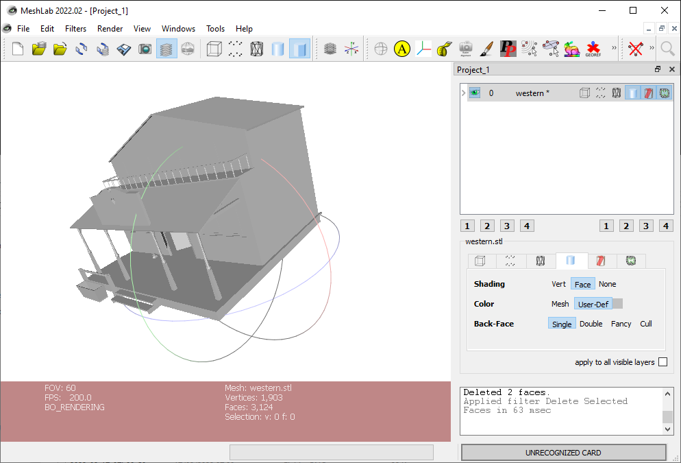
1/ you can export your model as STL file. Perhaps OBJ is OK too.
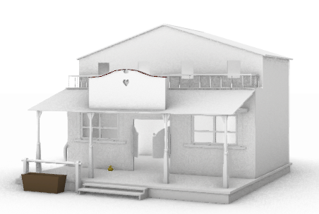
I don't have you file and took for the example a very old model of saloon, I made 30 years ago .
Hi Elang,
So with the different "types" of relief, you can go 2 routes. For "3d printing" i think you want to stick with "low relief" or bas relief.
For this you would use a program that can generate an "emboss" from a bitmap, 2d graphic. There are various methods. All the way down to just screenshoting your model. Poly modeling apps and cnc CAM apps usually have this ability
I think you can generate a somewhat "ok" model as a "high relief" inside of moi. But a high relief will not be great for 3d printing with regard to all the undercutting. If you wanted to take the time, you could probably "fix" the major undercut areas, for a 3d print.
To do a high relief in MoI, i would "rotate the model" to get the perspective you need in one of the flat views, then use the edit frame to flatten the model to the desired height.
I'll see about making a video to demonstrate the 2 options.
Hi Burman, thank you for your help. Definitely waiting for the videos.
However, I've tried rotating the model in the front view, but since it is ortho view, I can't get the perspective as it is needed. Is there something I'm missing here?
Hi Elang,
I think this is what you were looking for? I included the 2 scripts I used to make your perspective view a flat 2d workplace. Then Flattened the model to 2 units.
There is a bit of lag on some operations because I have my viewport mesh settings very high and the model is not a simple one.
I was a bit sloppy on rotating the flattened perspective back to a regular 2d view, but you could be more precise if you need.
I can show you a regular Bas Relief emboss in some other software if you need to see that.
Thank you very much for your effort in making the video. Appreciate it very much!
The thing is: in the final result (front view), the building has 'the same height' from left to right, while for it to be seen as 'correct in perspective' the leftmost part should be somewhat shorter than the right one. I tried to do it the same way as your video, followed by flow-deform it from a rectangle to a trapezoid. But it gave me an unexpected result (and took quite a while to process).
So I decided to simulate it with a simple circle, and here's what I got.
1. Choose the circle
2. Apply Deform > Flow
3. Pick the upper right corner of the square as 'base curve'
4. Pick the upper right corner of the trapezoid as 'matching end'
I don't use deform quite often so surely I'm the one who's mistaken.
Hi Elang,
"""""""The thing is: in the final result (front view), the building has 'the same height' from left to right, while for it to be seen as 'correct in perspective' the leftmost part should be somewhat shorter than the right one. """"""
Ah, i get it....
Not just a perspective emboss or relief but the model itself to actually be skewed.
I have included the 2 surfaces i used to flow. you can just copy and paste them or import into your model to be ready for flow.
Select model. then flow from square to perspective shaped surfaces.
I am not a projection specialist. The "Perspective surface" was created by me by drawing the lines. Maybe Michael or someone who is familiar can discuss drawing the trapezoid shape as an exact "Perspective".
For your flow issue. I dont think it likes a closed curves for a curve to curve flow.
You can create surfaces in that condition.
A simple planar surface wont work here. you need to make a surface with some parameters. I used sweep to generate the 2 surfaces I have attached. Turn on points for those surfaces to see the difference between a planar surface and a swept surface.
I just realized that we still have to work around the scaling (please forgive my English): so, for the arches, the nearer it is then the wider it should be. i.e.: the leftmost arch should be the narrowest compared to the others, and the rightmost should be the widest. I believe that I have to flow-deform the model once more (after narrowing the leftmost part) to achieve this... One step at a time.
Hi Michael.
That's very close to what I'm trying to achieve, expect for it to become a relief, the 'back part' of the model should be flat and aligned to the origin axis like so:
Please focus on the front and right views. All of its parts need to be extruded (based on the current Top View) along with the Z axis to the construction plane. So, the final model should be a single solid which qualified to be called as relief (that's what my 'client' said, and he is my little brother ^^)
Oh, and it is great if such a feature is added to the V5!
Thank you very much guys, for your help and attention.
re:
> That's very close to what I'm trying to achieve, expect for it to become a relief, the 'back part' of the
> model should be flat and aligned to the origin axis like so:
I don't think it's possible to achieve that just using a perspective projective matrix transformation as is being done here.
To produce geometry like you're describing I think that after the perspective projection you would need to generate silhouette curves and then extrude those silhouettes down to the base plane, like described here: http://moi3d.com/forum/index.php?webtag=MOI&msg=10568.6
It's probably better to do it using a depth map rendering + height field approach or zbrush where there are specific tools for it.