Show messages:
1-6
7-26
27-46
47-51
From: Frenchy Pilou (PILOU)
Here the height by Max Smirnov ;)
http://moi3d.com/forum/index.php?webtag=MOI&msg=7547.52
place file(s) inside the moi commands folder
relaunch Moi
Press Tab and write _heightmap
From: Phiro
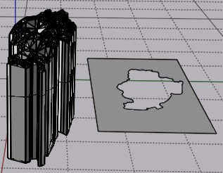
A problem you could have with your beginning object is the overhangs in the ground and the holes.
The overhangs gives only the higher point and hide lower points in depthmap. Holes give a 0 level, not an hole.
But the result could be like this 2 surfaces.
Yes Michael, you're right...
it's not an orthodox CAD software usage...

Image Attachments:
 2021-04-24_01h37_26.png
From: Michael Gibson
Hi Andy,
re:
> What are the steps to reverse engineer a structured object?
Draw lines for planar spots, use Circle or Arc through 3 points snapping on to triangle corners, use the lines and arcs to extrude surfaces.
- Michael
From: Frenchy Pilou (PILOU)
You can have easily some curves of your object
here the horizontal arounding after an extrude :)
make the same on some vertical sections planes on this same object
At the end make network...
From: Michael Gibson
Hi Andy,
re:
> What are the steps to reverse engineer a structured object?
There's an example here:
http://moi3d.com/forum/index.php?webtag=MOI&msg=9208.1
- Michael
From: Andy (ANDYA)
How about this?
1. Create object of precise shape and size
2. Slice object using surface to create the back of the object
3. Offset surface X mm
4. Slice object again with surface to create the front of the object
I.e. splitting the object into three parts and keeping only the middle.
Is that possible?
Andy
From: Frenchy Pilou (PILOU)
Of course yes but it's completly different that you want to make with your "triangulated" object! ;)
If you create directly with "Nurbs" curves, Surfaces etc ... you will not have problem!
From: Michael Gibson
Hi Andy,
re:
> Is that possible?
No probably not easily if the "surface" is a bunch of triangles instead of an actual smooth surface. It will be difficult to offset something like that.
- Michael
From: BurrMan
Hi Andy,
So your surface looks like Crumpled paper!!!
I opened it in 3dcoat without modifying it. Then I ran a command called "Instant Mesh" with the auto setting. I set 3200 as the poly count. If you really wanted or needed quality results, you would retopo it properly i guess.
The result below.
The retopoed mesh along side the same file imported using MoI's SubD tool:

And the Imported Mesh, alongside running Max's SubDiv9 on it.

In both cases, the imported mesh is there by means of Max's ImportObj Command.
I wouldn't try to work with the original 3dm file....
Image Attachments:
quick_redo.jpg
quick_redo_subdiv9.jpg
From: Andy (ANDYA)
Thanks BurrMan and to everyone who replied.
Here is what I just tried.
1. Open obj in meshlab
2. Go to Filters -> Remeshing, Simplification and Reconstruction -> Simplification: Quadric Edge Collapse Decimation
3. Enter target of 1000 faces
4. Export obj
5. Use Michael's obj23dm converter, choose closed polygon for each face
6. Load 3DM into MoI
7. Select everything
8. Choose Construct -> Planar
9. Save as 3DM
10. Open desired part in Alibre Design
11. Import 3DM surface
12. Trim model using surface
13. Move surface
14. Trim model using surface (reversed)
15. Export as STEP
16. Load STEP into MoI
17. Delete surface
Alibre Design is ACIS based and doesn't like triangle-based geometry but it seems to cope OK with slicing an ACIS object with a triangular surface.
That's a lot of messing around, would be nice if MoI had this trimming function as well.
Andy
Image Attachments:
ADSurfSlice.png
ADSurfSlice.png
From: BurrMan
If you can drop it down to 1000 faces for the retopo, you can bring the surface into MoI and Shell it there too.... Did some booleans, etc. too.....

Image Attachments:
shelled from 1000.jpg
From: BurrMan
Clean....

Image Attachments:
hidden edges.jpg
From: mdesign
Thanks for bringing that topic. I create new designs basing on 3d scans often. I use Zbrush, Modo, Rhino, MoI3d.
I have some thoughts about workflow. Maybe it doesn`t help you directly but I hope it will be helpful.
I think that not always is worth to move scans from polygon to nurbs. If you want thicken and trim it only it`s super easy in most polygons apps. I would do this in Modo or Zbrush but it`s also easy on Blender or MeshMixer.
I had one work few years ago where I decimated scan mesh in Zbrush and imported to MoI3d with Max Smirnov OBJ importer. Next I`ve created curves with using "on surface" snapping to create solid model after. This was no super exact but good enough to make that specific hard surface model. This model was prepared for CNC machine and they demanded STEP file. That`s why I have not made it in polygons.
May I ask why you need that surface in NURBS?
Sometimes I do retopo by hand over scan in polygons to have subd cage and I import it to MoI3d (native subd importer or scrip[t). If surface after import is not good enough then you may build new one over that surface in MoI (second retopo in nubrs this time).
Sometimes I sculpt scans in Zbrush before doing auto retopo (remesh) to have better surface for remeshers.
Sometimes I cleanup mesh errors before I bring it to other software (self intersections, ngons, non-manifold edges and polygons).
Sometimes I use remesher to leave all bad topology behind. Sometimes it is so bad that only manual method is possible.
I think CAD is not friendly enough for meshes to play with it so I try prepare meshes earlier in more friendly environment. But it`s my approach. Maybe it`s bad.
Sometimes I do quad remesh (there is free instant meshes but I prefer Zbrush Zremesher). You can import that quad cage as subd cage into MoI3d and it will also convert it to patches.
When I see so organic shape as yours I have so many questions in my head. Why nurbs? Is it prepared for CNC or for 3d printing or maybe only for render?
From: Andy (ANDYA)
Thanks for the reply - yes I need output in a CAD format for machining or 3D printing and ideally further processing in an MCAD package.
My example was a simple one but I need to create precise parts with bolt holes, etc. that fit over the top of a surface, so it's not just thickening.
For MCAD I use Alibre Design. For organic I would use Blender (if I ever did that kind of work). I thought that MoI inhabited the area in between where organic shapes were easily created in CAD formats. Alibre Design really struggles with organic stuff and extruded text in particular.
Andy
From: mdesign
1a) practice some manual retopo method (it`s bullet proof but time consuming) :
https://www.youtube.com/watch?v=BEwEWKOH5ws
If you will want sharper edge you should do smaller polygons or add additional edge loops.
1b) use quad remesher in Blender -
https://www.youtube.com/watch?v=p_iLzSWMbP8 or InstantMeshes software.
2) import quad cage as subd to MoI3d. MoI has better subd>nurbs convertion than Rhino (IMHO)
If you will do proper retopo work you will loose mesh errors from scan. Surfaces will be much cleaner.
One additional note: some surfaces made in that way might be too dense and have too many control points to be well thickened or edited in Alibre. I`ve tested few parametric cads on some surfaces made in this way and this is not so simple answer. Best would be old school traditional surface built from low count of CP. Dense CP surface = problems during edition (thicken and offset may fail sometimes).
Please give some tips if you will find is it working for you or not.
From: Michael Gibson
Hi Andy,
re:
> I thought that MoI inhabited the area in between where organic shapes were easily
> created in CAD formats.
That's not too far off but the focus in MoI is on drawing new things from scratch. Generating organic shapes that adhere to scanned triangle mesh data is a different area than that - "reverse engineering". That is not an area that Moi is focused on, it's a big area with specialized tools and workflows and a high learning curve.
It seems that maybe you heard someone mention that you can create organic shapes in MoI using tools like network surface and you are seizing on that word "organic" and expecting that Moi can do anything having to do with any organic shape process at all which is not accurate.
For reverse engineering like you want to do probably Rhino with some of the plugins I linked to above is your best bet. This is a good starting point:
https://wiki.mcneel.com/rhino/reverseengineering
There are automated scan to CAD tools like Geomagic wrap but they're pretty expensive.
The other route that you can go is to do more work in the polygon mesh world like with 3D Coat or ZBrush and either do all the work for preparing your output there or use retopology tools to fit a sub-d mesh to your scan data and then bring over the sub-d surface into the CAD side of things.
MoI may be able to play some part in this process but it is not going to be a tool that does the complete reverse engineering task on its own.
- Michael
From: Frenchy Pilou (PILOU)
Refining & reduct the process! 7 Steps! :)
- MeshLab
1. Import the file OBJ triangulated
2. Go to Filters -> Remeshing, Simplification and Reconstruction -> Simplification: Quadric Edge Collapse Decimation
3. Enter target of 1000 faces
take the result without exit Meshlab
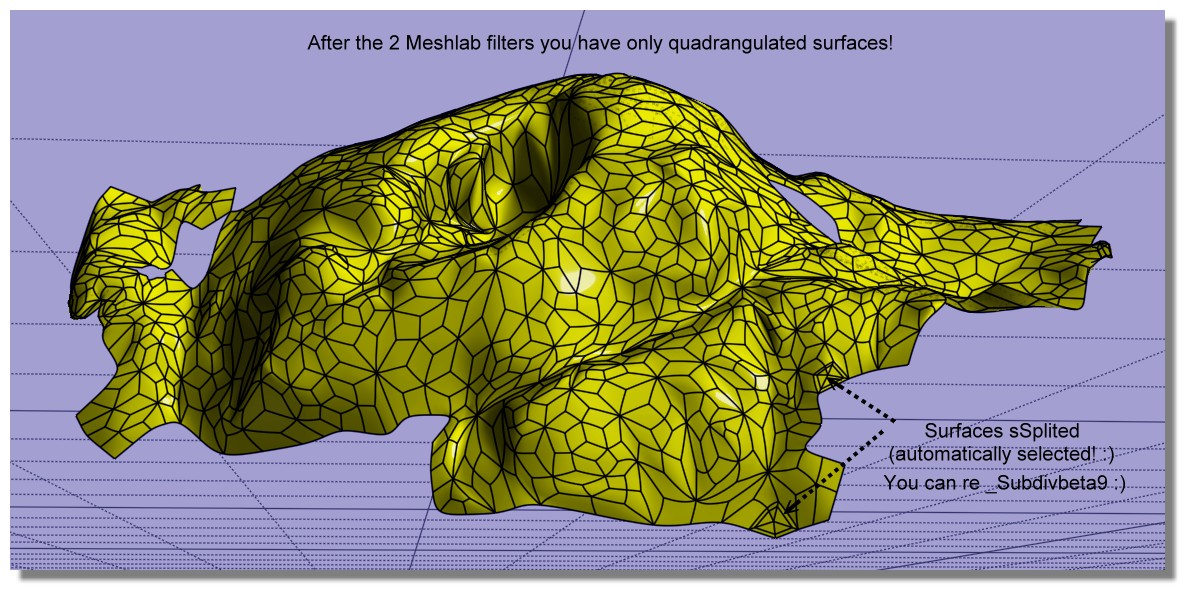
4 . now again MeshLab : Tri to Quad (4-8 subdivision)
5. Export obj (with enable Convert Triangles to Polygons)
- Moi3D
6. In Moi SUbD / Create from File (because _import obj don't work ! )
7. _subdivBeta9 (only 3 surfaces to sSplit automatically selected! )
you have a perfect voluptuous nurbs surface! :) (facets are not planar! )
From: Michael Gibson
Hi Pilou, although your method there does create quads, they are not in a configuration suitable for sub-d smoothing. You've got a large number of "star points" and no long sequences of edge flows like an actual sub-d control cage should be like.
So I would not recommend that route compared to doing actual sub-d focused retopology.
- Michael
From: Frenchy Pilou (PILOU)
That the default! :)
From: Barry-H
Hi,
have been experimenting with Meshlab and Instant Meshes and got similar results To Burrman.
Maybe of some use.
Cheers
Barry
.png)
.png)
Image Attachments:
Screenshot (614).png
Screenshot (618).png
Show messages:
1-6
7-26
27-46
47-51