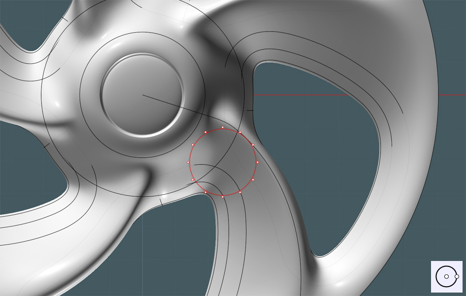
Now we need to put some lug bolts near the center. If you know the proper measurements, this is the time to mark the correct positions,
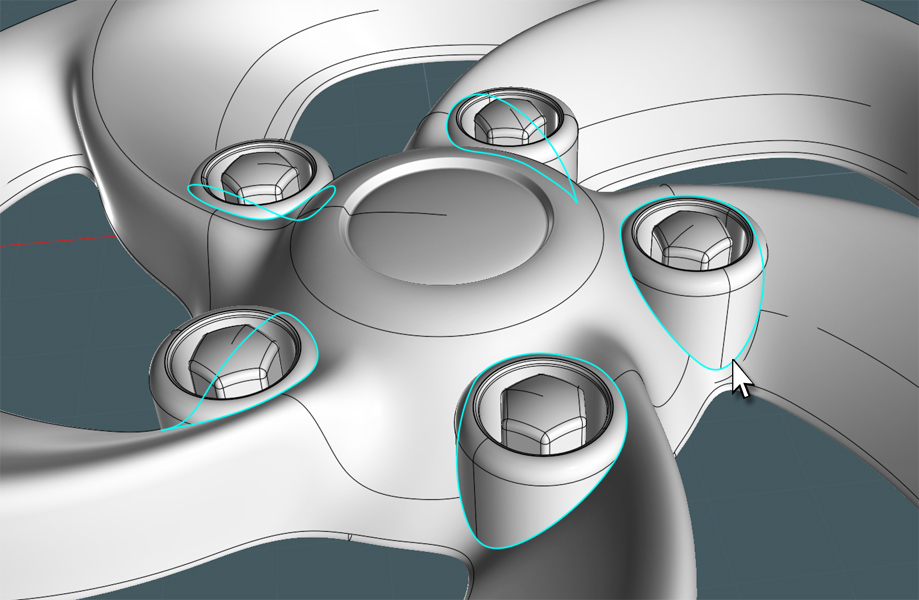
I tried different configurations and shapes for places to put the lug bolts, but I found that a round shape would match the curvy shape
of this rim. Create a circle that is larger than what the bolt would occupy.
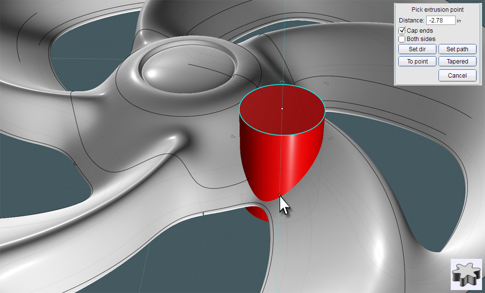
I've extruded the circle down through the rim's surface.
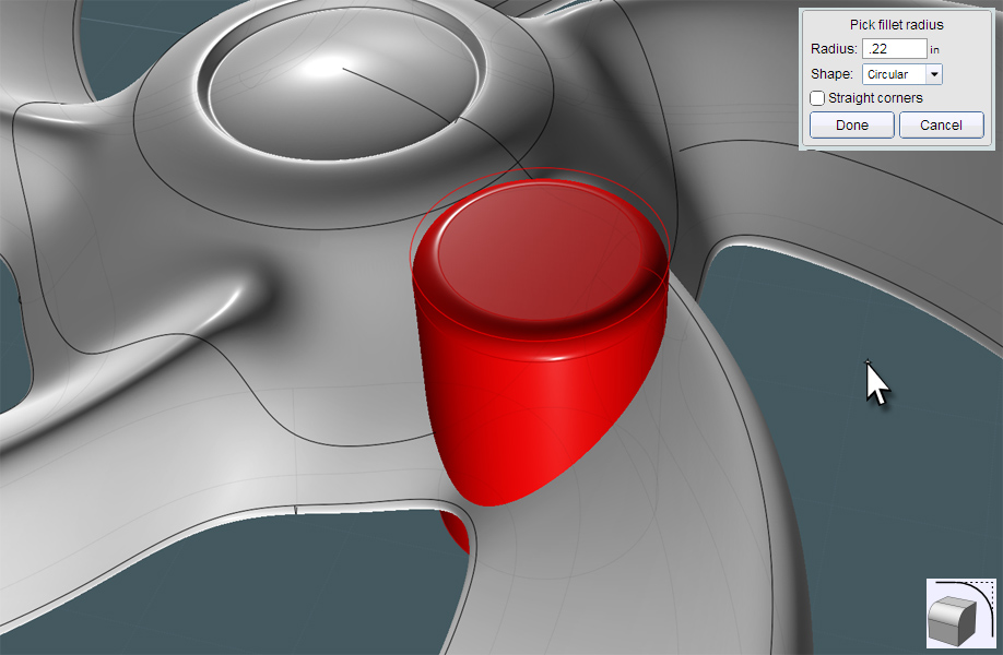
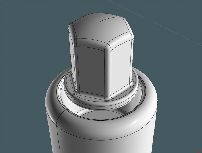
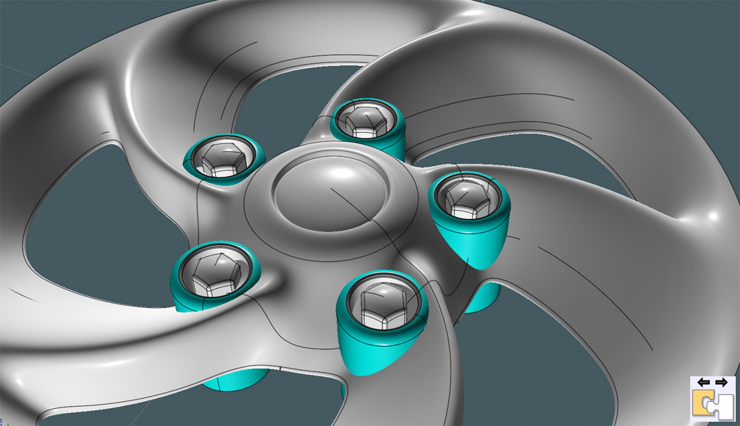
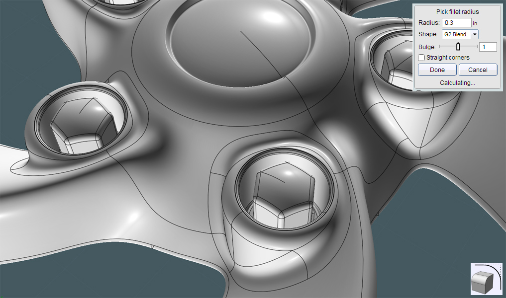
Fillet the top of the new cylinder.
I will not explain how to make the part shown here. This is where your skills and creativity come in... ;-)
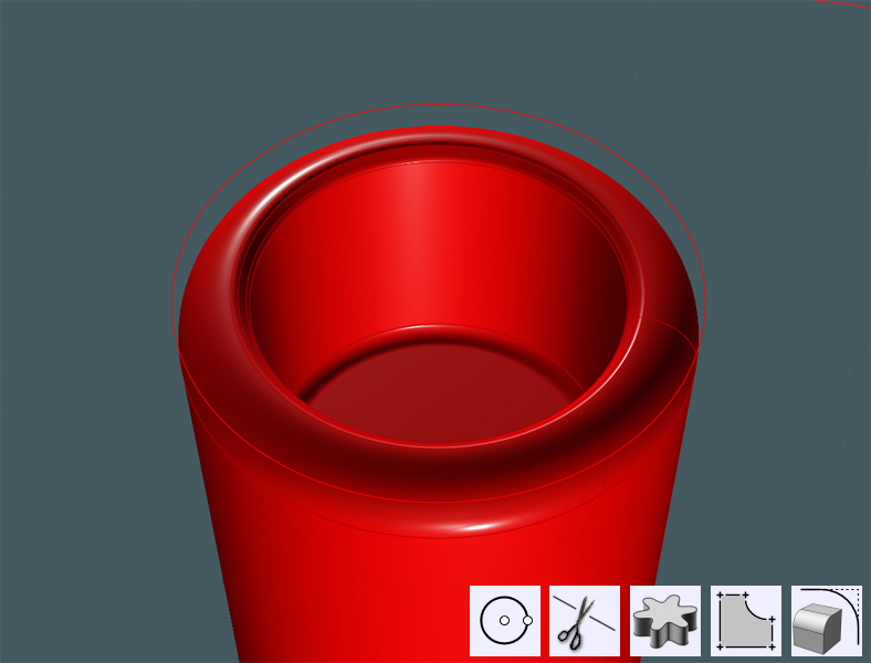
Make your lug bolts or caps... You can use the ever popular example at this linked post to learn how to best make your own:
http://moi3d.com/forum/index.php?webtag=MOI&msg=5062.8
![]()
Move the assembly down, so that the mid-surface region of the top fillet sinks into the rim object surface.
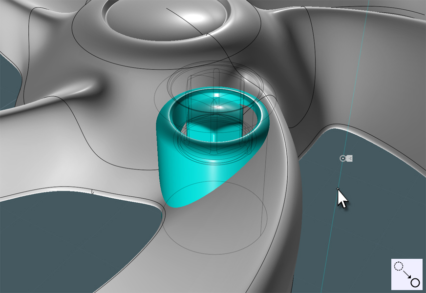
...as shown here.
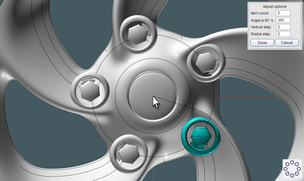
Copy these assemblies around your model by using Circular Array, using the origin as the center from the TOP View.
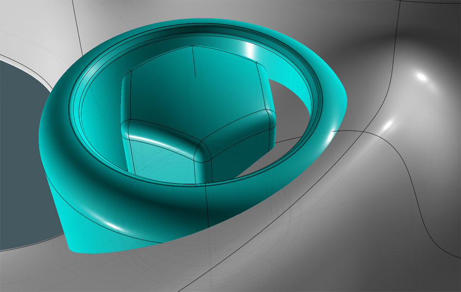
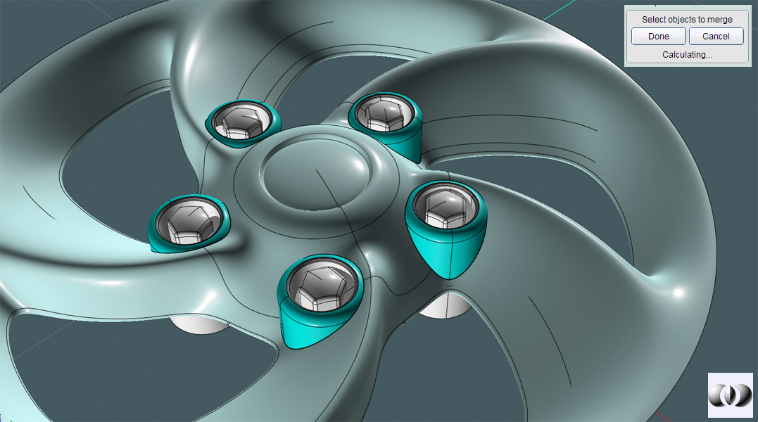
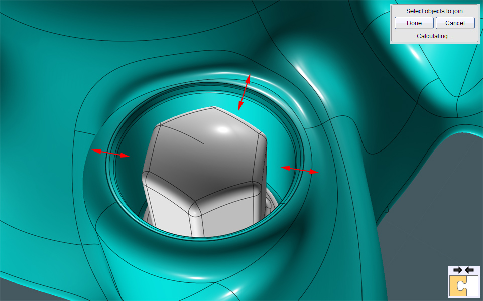
We need to now 'marry' the lug receptacle shape group with the rim's surface.
It will be easier if you separate the main set of objects from this part...
Results will vary... I used Boolean Merge to intersect/trim the two sets of surfaces with each other.
They are not enclosed solids, but compound surfaces, so this gets tricky. There are also other adjacent surfaces that complicate things.
You can try combinations of other Boolean modes plus some copy and paste, but intersecting a curve between surfaces
and Trimming them from each other will work as well.
You may have possible corruption and artifacts that will take a bit of patience to work with...
...Noting the bottom of the model, there are a lot of scraps. Some are quite corrupted. Select and and delete these.
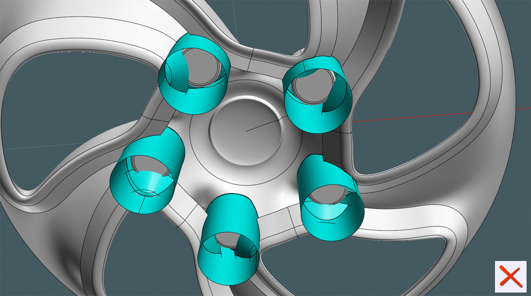
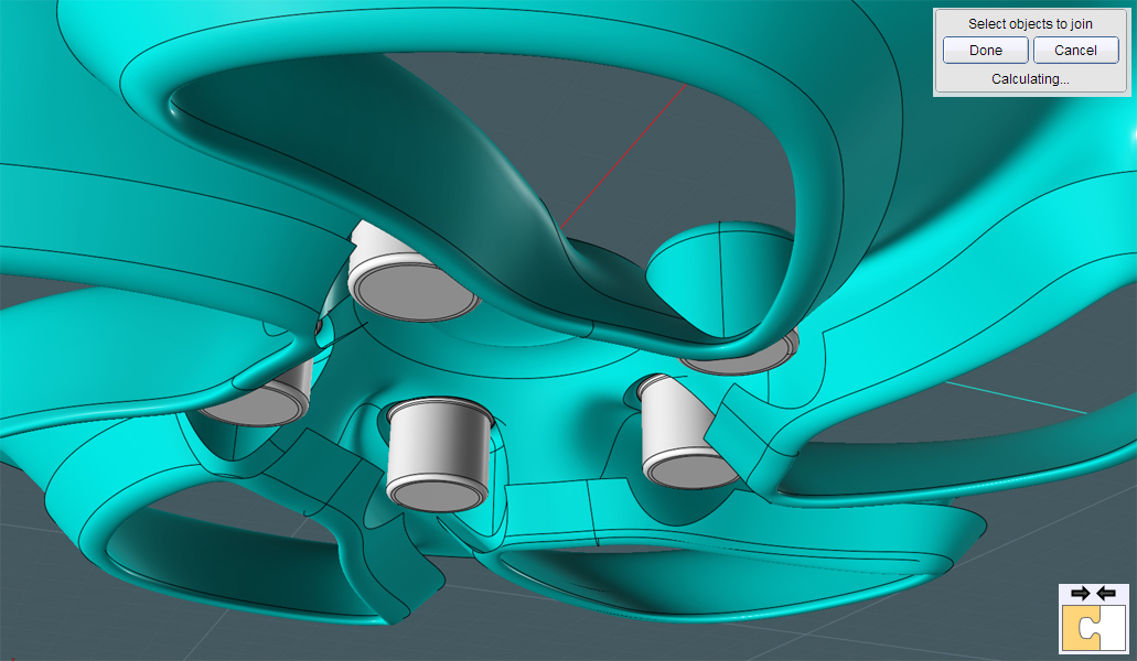
Join these main surfaces together...
Notice that I arranged these shapes to be trimmed within pretty opened areas away from sharply angled and densely populated seam areas.
...For Fillets -
seams baaaad!
A G2 Fillet did a nice job on smoothing the 'lug receptacle' object into the rim's main surface.
There are some glitchy areas. I think by this Beta release, there were issues with some edges of Fillets,
but they are almost not noticeable in this example.
When you Fillet around odd angles and joined edges with poor continuity you'll often run into issues. This is to be expected.
Join your lug receptacle's guts back to the main surface.
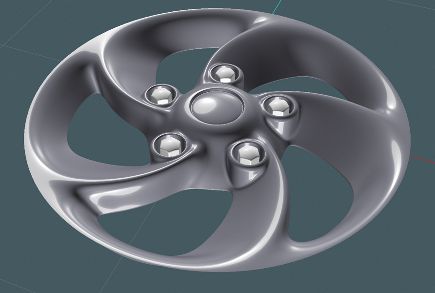
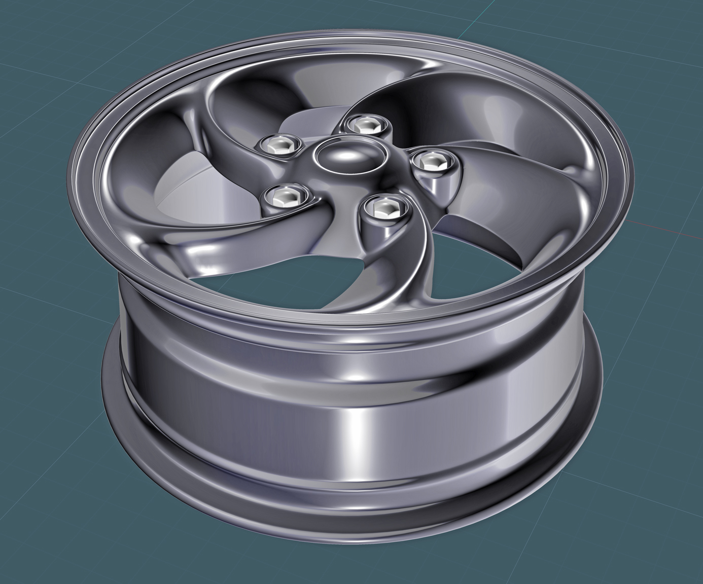
The major rim is now completed. Looks nice...
We'll now get to use the Image command in the View tab.
Here, we'll derive a real-world shape configuration for our model using a diagram found on-line.
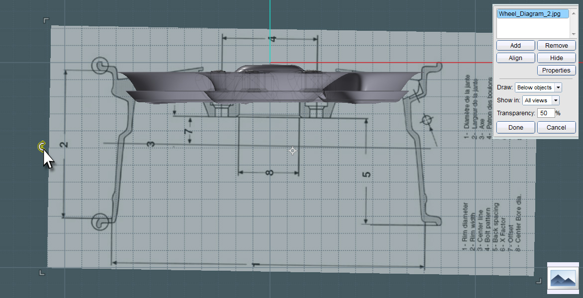
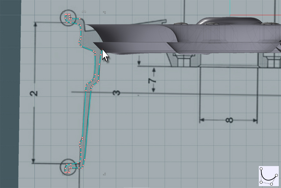
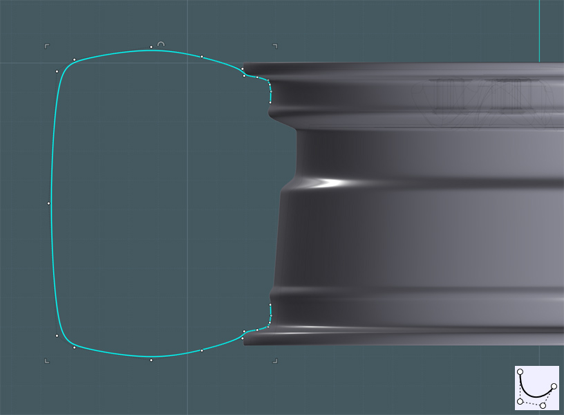
Draw a profile for the main rim's shape.
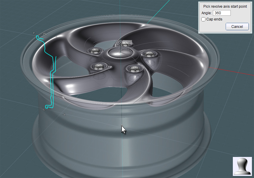
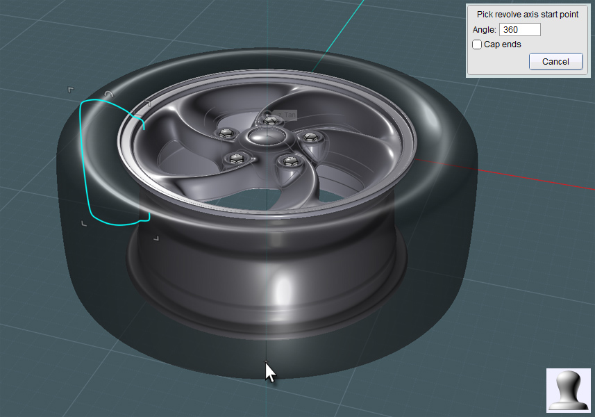
Revolve this profile.
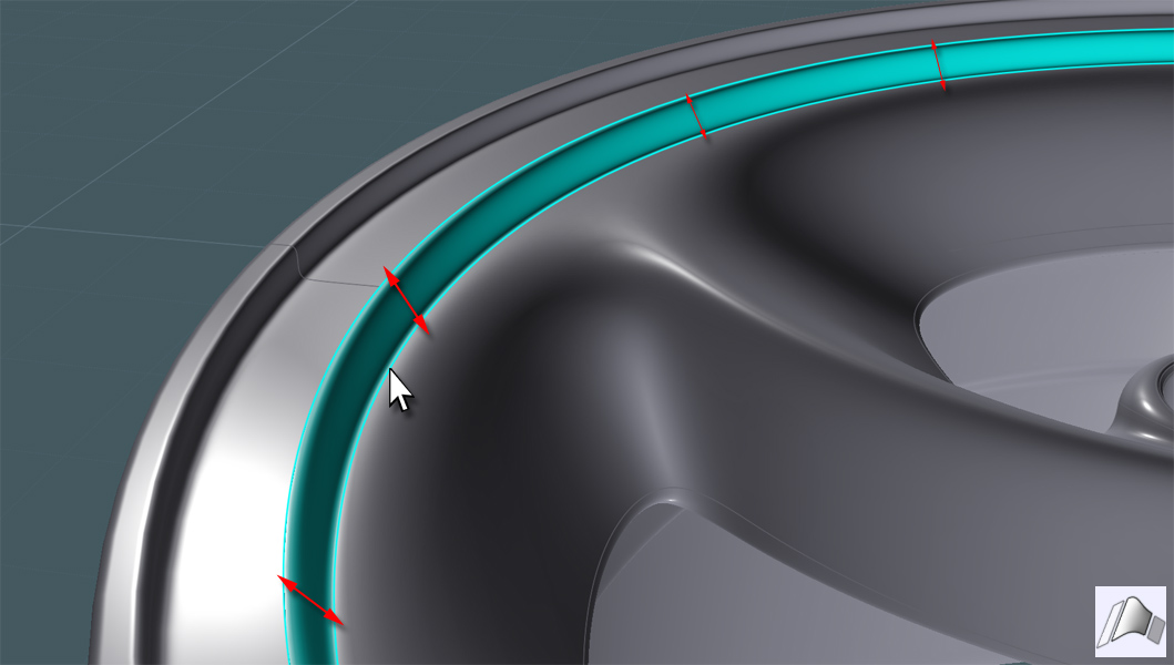
Blend the rim's surface shape and the revolved body shape together by making a Blend between the two edges.
Join them together once made.
Very good! This is your basic completed car rim model.
Now lets throw a tire (tyre) on this rim.
Create a profile shape for this that represents a cross section of your tire.
There should be a slight arc to the tread-face of the tire. This 'bulge' becomes relatively flat
once weighted on the road's surface with proper inflation pressure.
We'll plan on flowing all kinds of
tready goodness to the shape we wish to Revolve.
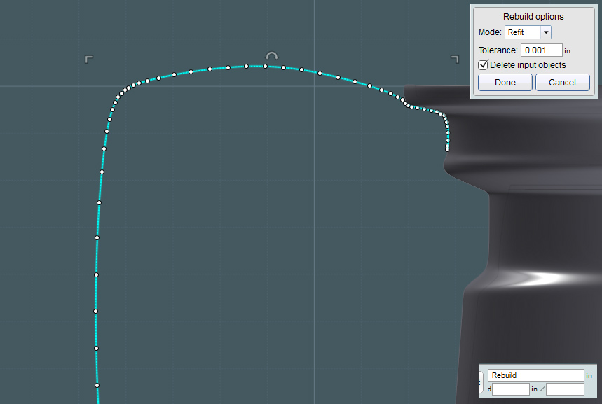
In my experience, and with Michael's help, I've found that the Flow operation works more consistently between the reference and target shape
if the associated profile curves have been Rebuilt using the "Refit" mode. In "Refit" mode, the curve and its hidden 'weighting' attributes are better
dispersed. This spatial dispersion translates to any surfaces created from these curves.
Revolve this shape... Right after Revolving this profile, you can use its history to tweak the overall shape and proportions of the tire body.
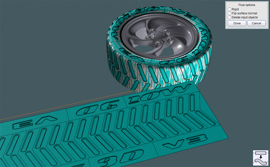
Time to Flow the tire detail!
You say, "all you gotta do is make some tread parts and flow it".
Well, we at least have to make sure that what me make on the flat reference surface looks roughly the same
when we flow it around the circular surface.
The best way to ensure that is to make the reference surface the same dimensions as the revolved surface, if the revolved surface was rolled flat.
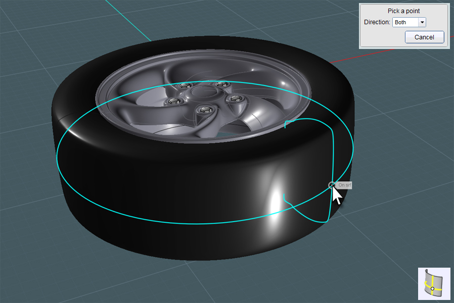
Here is a good use for the new Isocurves command:
Sweep the Isocurves preview around somewhere in the middle of the revolved object with "both" directions in action.
Now we simply use a little script of Michael's called UnwrapCurve:
http://moi3d.com/forum/index.php?webtag=MOI&msg=5136.1
When done to the result of each isocurve creation, we will know the exact physical dimensions of the revolved surface.
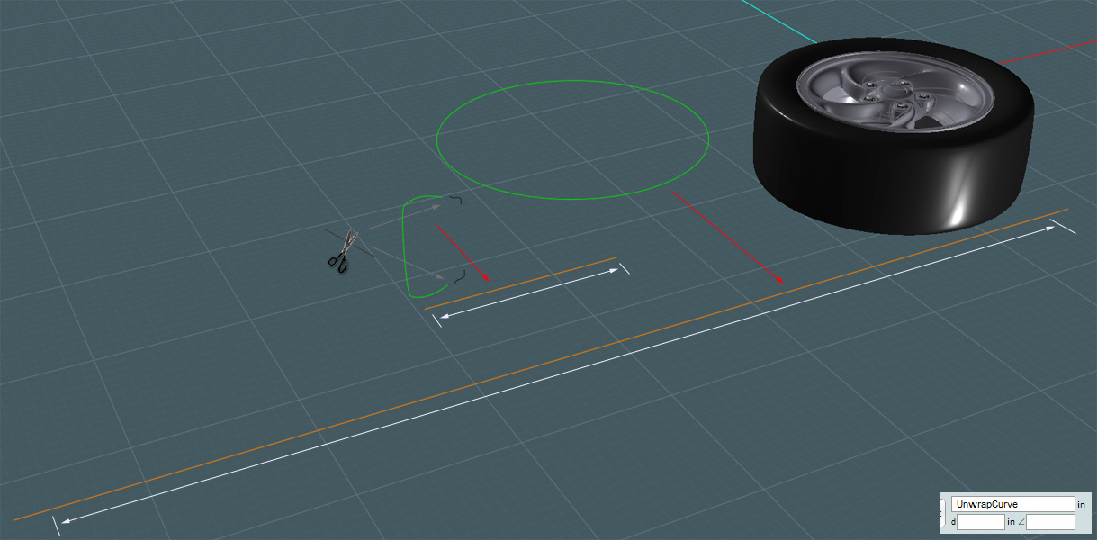
Here we create a 'reference' Plane in the same dimensions.
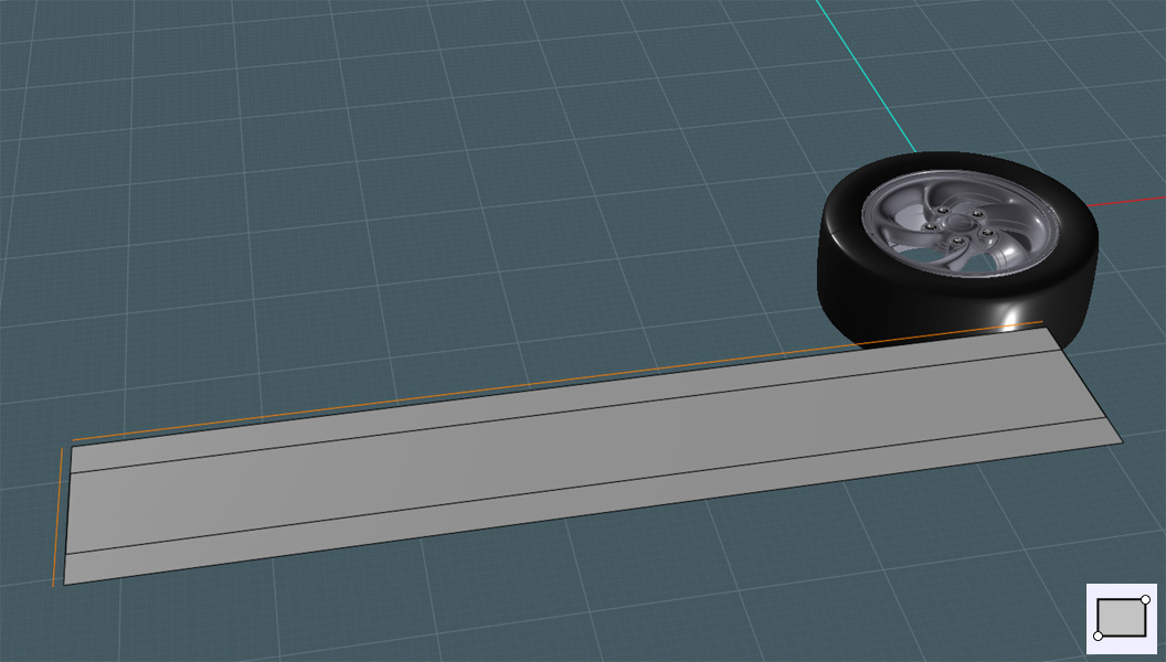
Once you create a pattern for the treads and additional objects like recessed type - once Flowed to the revolved surface,
the result should be very close in proportions to the dimensions you designed them in.
Keep in mind that while the tread itself would be best made from actual NURBS objects, subtler details like
sidewall type might be best done as flat co-planar objects, with each object of both the type and the tire surface given a different materials
in the rendering program. For instance, the tire material itself could be made with a dull rubber-like material
with a little 'displacement' and the recessed type could have a flatter, slightly glossy rubber material.
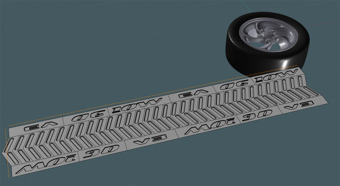
In my example shown here, the tread and associated type were cut into smaller more manageable sub-sections.
Flow may have a better 'go' at working these smaller regions rather than having to negotiate a large surface with many compounded
and trimmed sub-objects. (Additional copying and trimming in this example was done prior to Flowing.)
And here you can see the immediate result of the Flow operation on the revolved tire object.
This is pretty much the final product of my tutorial for the "Turbine"-style car rim and tire.
From here on, you could add smaller details to your own model such as a Schlader valve and those little
'nublets' that stick out like short porcupine quills on brand new tires. And then followed up with even larger elements such
as disc brakes and other car parts.
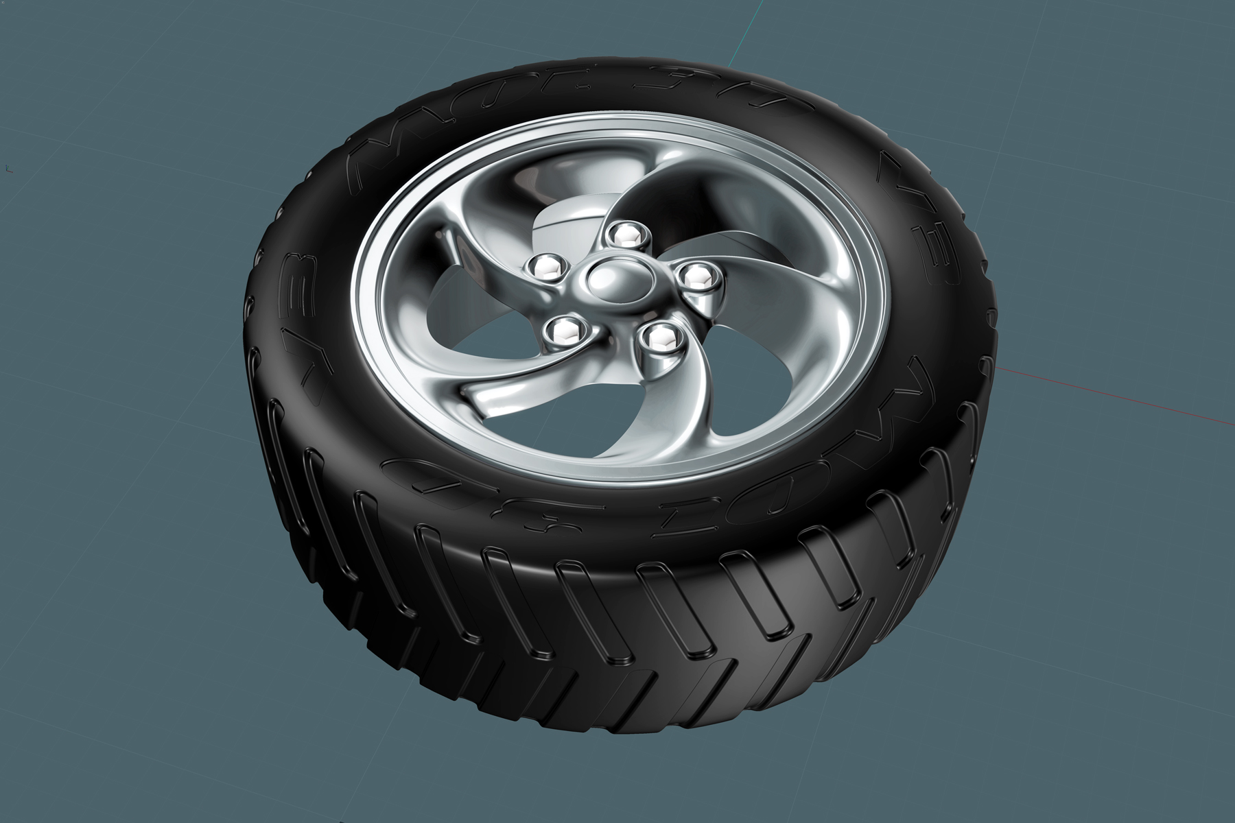 The above final pic was made using multiple photoshop superimposements from MoI's UI screen capturing script
along with different lighting combinations.