Hi gang, I finally get to produce another Moi3D tutorial! It's been a few months.
Make this pro-looking "Turbine"-style sports car rim with tire:
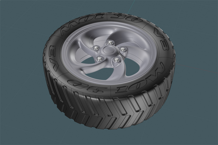
This model will make good use of some of the newly added features to MoI V3's Beta.
This tutorial's purpose is to only give the modeler some pointers and inspiration.
I can't guarantee that following this tutorial will yield the same result or be free of the many pitfalls and glitches common to a NURBS modeling.
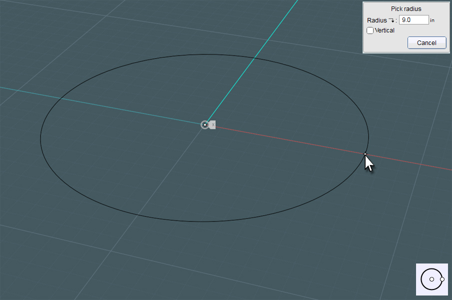
First draw a circle in TOP View. I suggest working everything to real-world dimensions.
To make our fairly complex "turbine" shape, we'll be stating off by actually editing a NURBS surface!
NURBS surfaces are defined by control point grids and trimmed edges, so we'll need to define an 'N'-number of control points to work with.
The circle you create will be made with a pre-set number of control points. Twelve in this case.
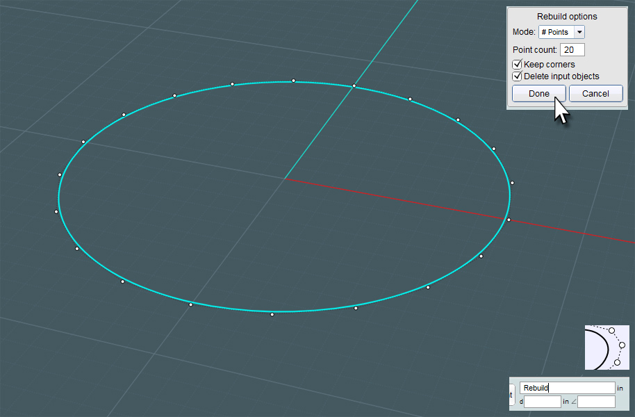
Enter the word 'Rebuild' in the command entry field at the bottom of the MoI interface.
I suggest assigning a keyboard shortcut to 'Rebuild'. I use [Alt-R].
NOTE: Looking at the model example above, the main turbine shape has five "mags" or pillars and five holes.
The number of control points and the ratio of points selected and not selected will determine the number of pillars and their relative shape.
In this case, I start off by Rebuilding the circle to have 20 points.
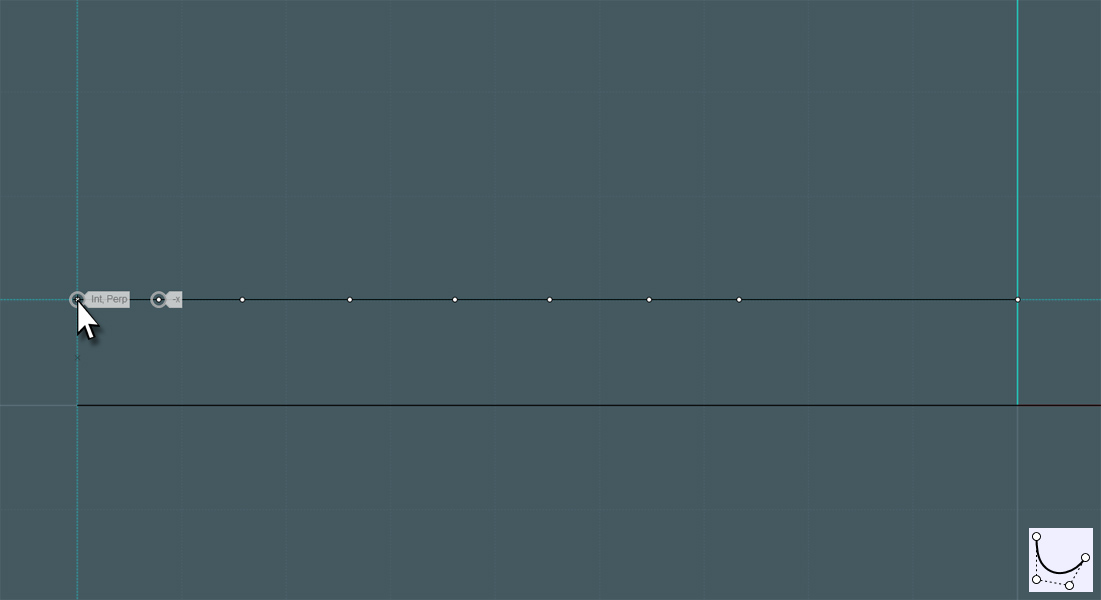
Go to FRONT View and draw a curve, starting from the center (origin) of the circle with a planned number of control points
and work your way to the side. A few extra points near each side with help buffer and define the points we need to work with.
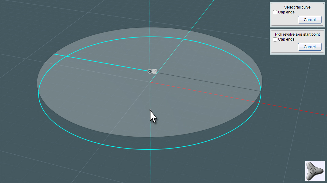
Let's Revolve by Rail... Select the curve and use the circle as the rail. The center origin will be the axis.
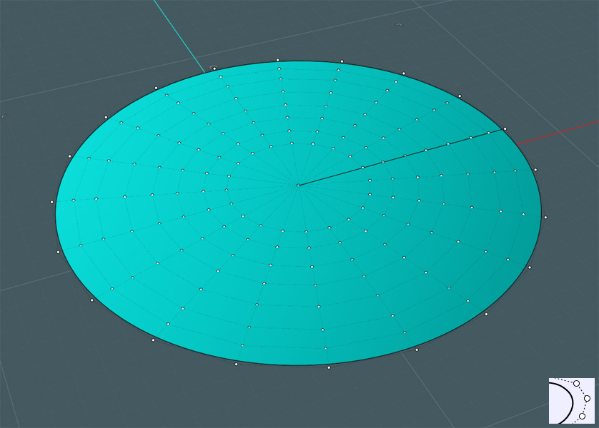
Show Points to see the control point/grid structure of the new circle plane.
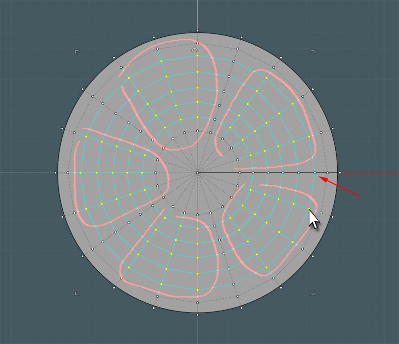
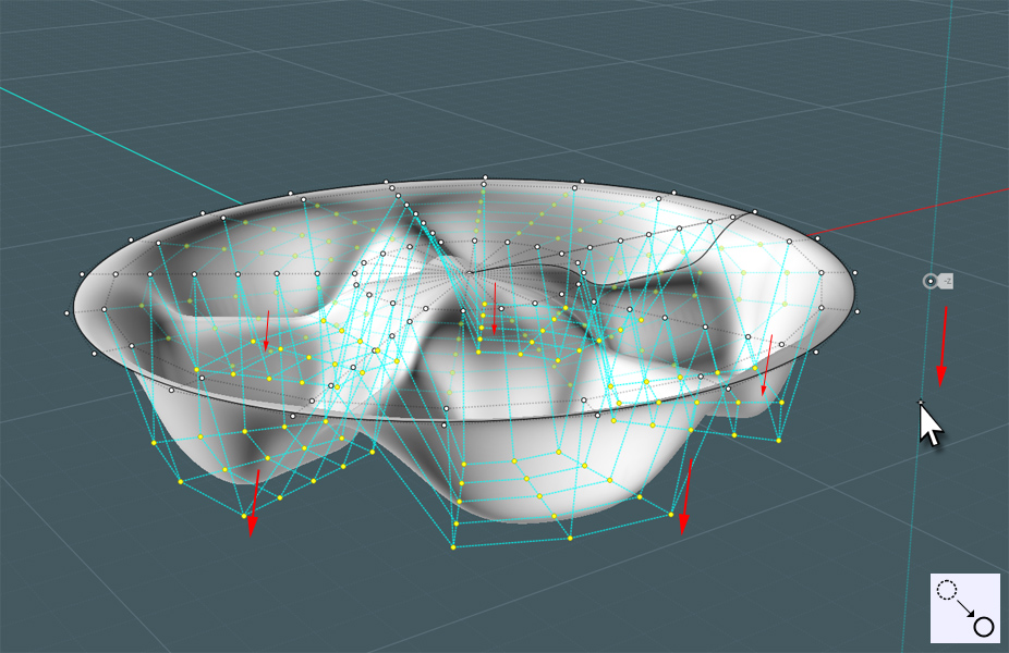
Here is where your personal touch comes in... Note the picture below: I've selected concentric groupings of points in the
structure that have a logical arrangement to them. Leave at lease two radial rows unselected - in the inner and outer regions -
to act as a buffer and also at least one 'spoke' line (from center on outwards) of points unselected.
In the Z direction, Move those selected points away from the normal of the surface (as shown). The distance is not critical.
Notice that there is now some kind of dip in the new ridges. We don't want them in this model, so select the adjacent un-moved
point groupings in the 'spoke' areas.
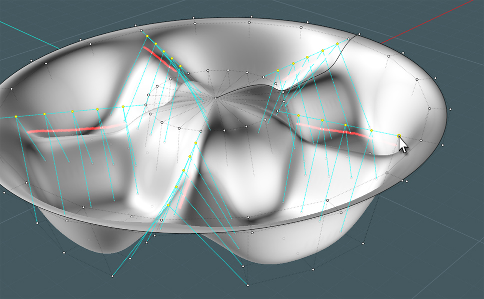
Move those in Z upwards until the ridges levels out.
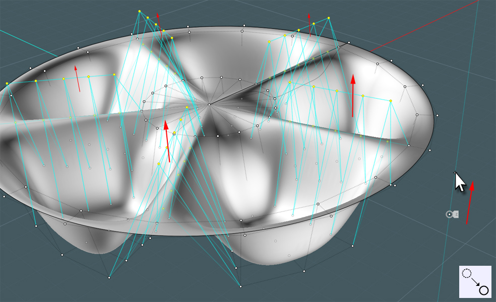
We are now ready to give this new "(baking) pan" shape that 'turbine' look.
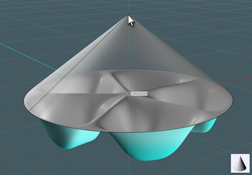
Trust me with this... We need two cones, so use the defining circle of the shape to make a cone that is the same diameter and
is planted right at the top surface of the shape.
Make a copy of the cone and move it above, but don't forget to delete the bottom plane circles that cap the cones.
We just need the cones.
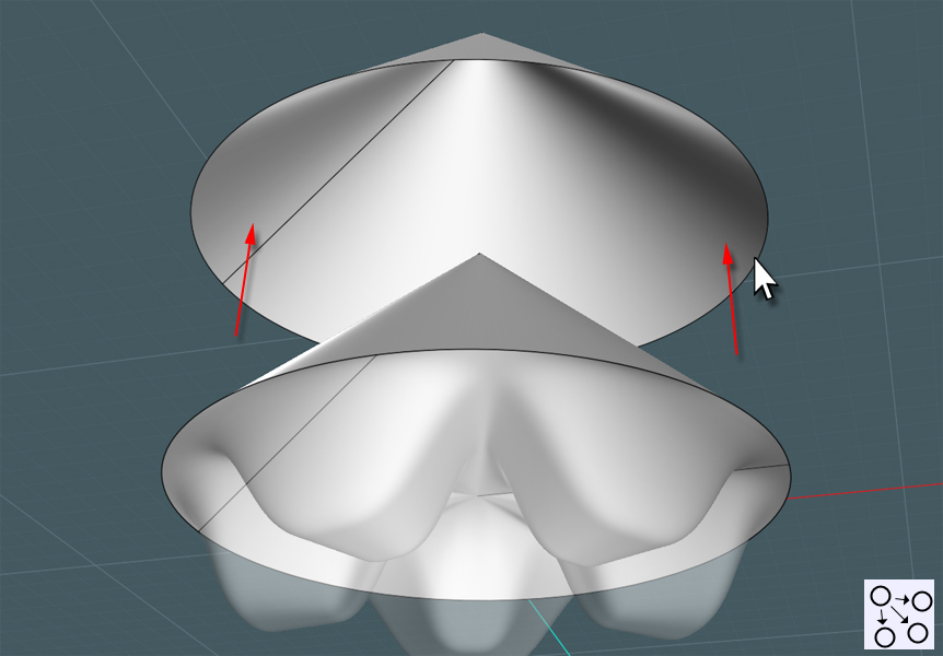
Using Moi3D's Version 3 Beta - We are going to twist the top cone along its total center axis from the point to the center
of the bottom circle. I used 60 degrees, but this is up to the modeler.

Now go to the FRONT View and use the handle-bars to [FLAT]ten the cones!
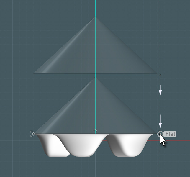
Inspect the point structure of the two cones. The top surface has a 'spiral' pattern and the bottom one has a version of the
special kind of cage that makes simple revolved primitives. This is what we want.
This is where we use the Flow tool... Please study my tutorial: "Twirl (or Whirlpool) An Object using V3's Flow Command on a Revolved Surface"
http://moi3d.com/forum/index.php?webtag=MOI&msg=4647.1
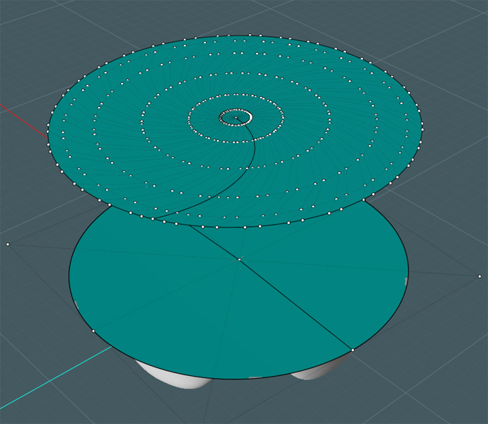
Select the pan shape object and execute the Flow command. Select a relative area near the seam or side edge of the reference surface.
The 'reference' surface is the bottom circle nested on top of the pan shape. The 'target' surface is the spiraled circle at the top.
Note the new twirled version of the pan shape.

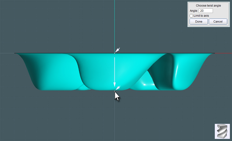
Now to use the V3 Beta's Twist tool again: Twist the pan shape via its center origin axis and do so at about a third of the spiral twist.
I used 20 degrees of Twist.
An enclosed "pan" is good if you want to make models of kitchen utensils, but we want to make pillars for a tire rim.
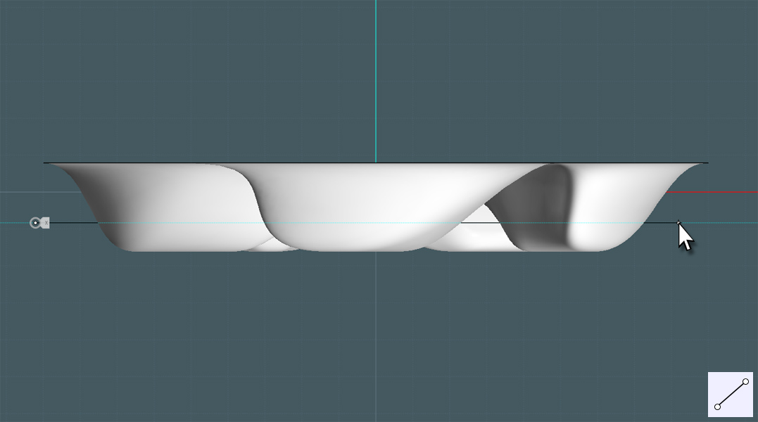
Draw a line from FRONT View where you want to cut the bottom parts off of the shape.
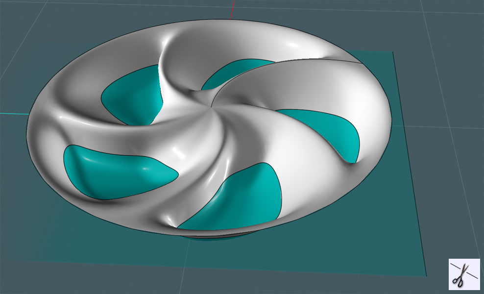
Use Trim to cut the bottom regions off of the shape. You'll now have holes!
Here is where things could get tricky... If you were going for a complete model, you would need to define some thickness to this shape.
You could do it with Offset, but when I tried, the results were not good.
So we'll need to "fake the funk" and create some way to give the appearance of thickness.
Which is all we need if we are only just to use this model for rendering and concept creation.
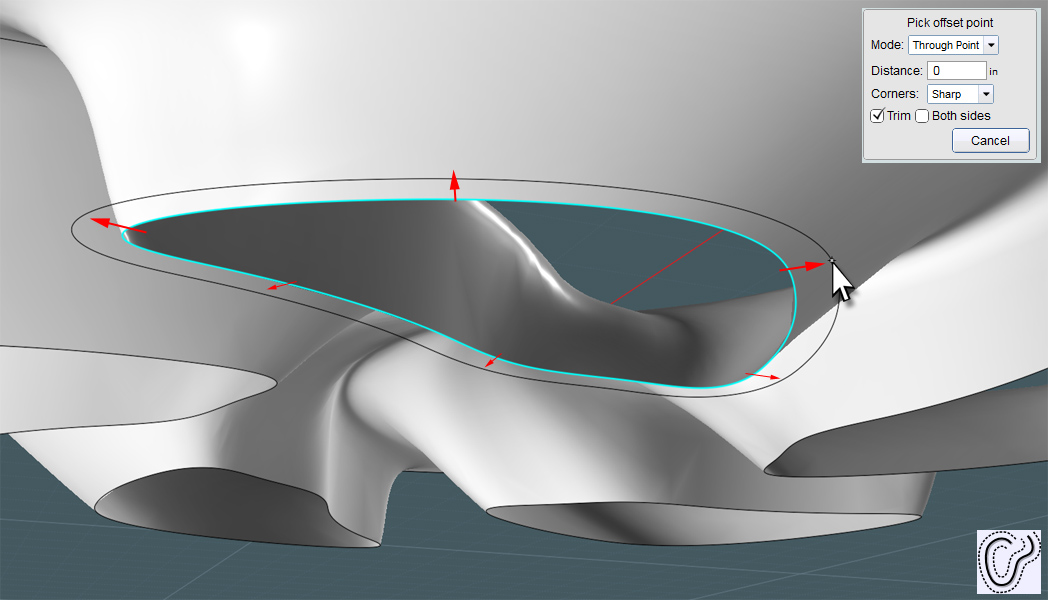
Select the hole edge trim curve and just Offset it. This will be your mock thickness.
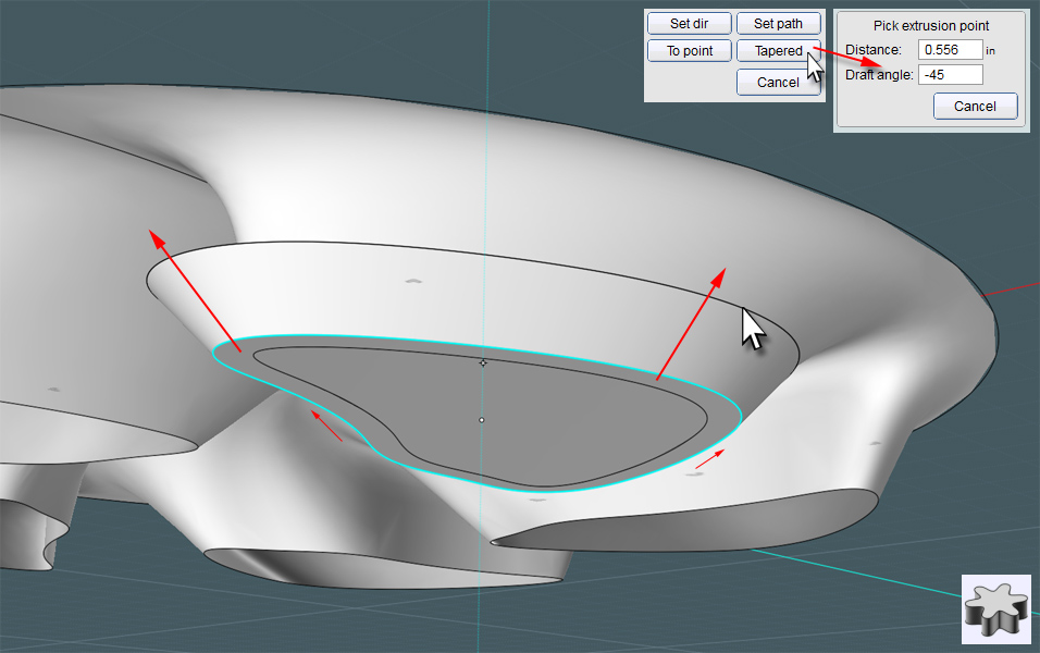
Another NEW MoI3D V3 tool! :-)
Extrude the offset curve using the "Tapered" Draft feature. Use an angle that approximated the tapered quality of the shape's opening.
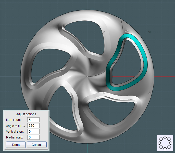
Make Circular Array copies of this drafted extrusion to match the openings arrangement.
Use the Blend tool to create a bridged surface.
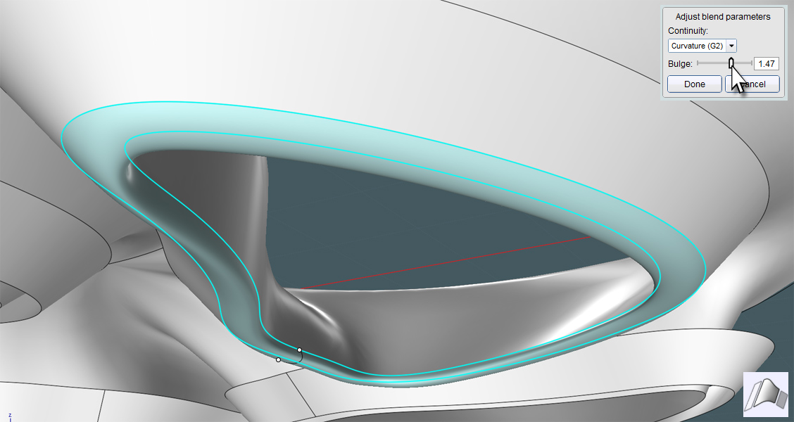
Join those surfaces, and now you have thick areas to the opening areas of the shape that may show up in a rendering.
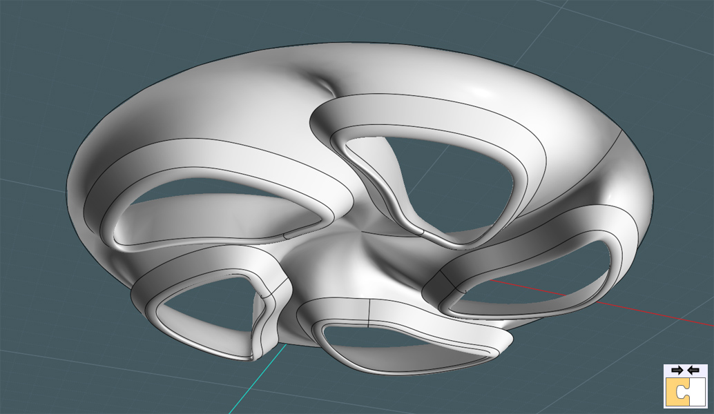
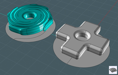
Unless you are happy with this cool 'star' shape at the center of the rim, we need to re-construct something nice looking there.
You can simply first cut a small area by trimming a circle - but I thought this would be a good time to use the NEW MoI V3 tool:
Trim by Isocurve!
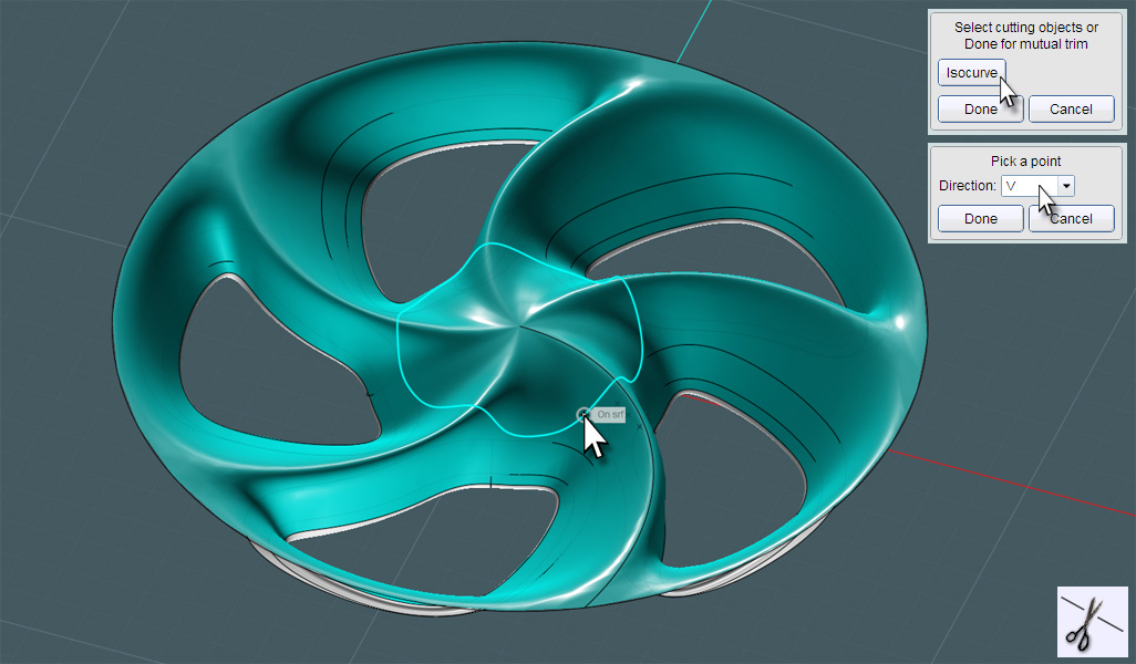
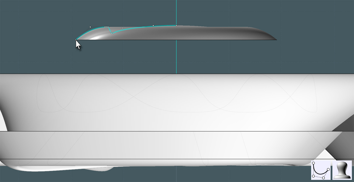
Make a profile curve to match something you would like to see in the middle. Revolve it.
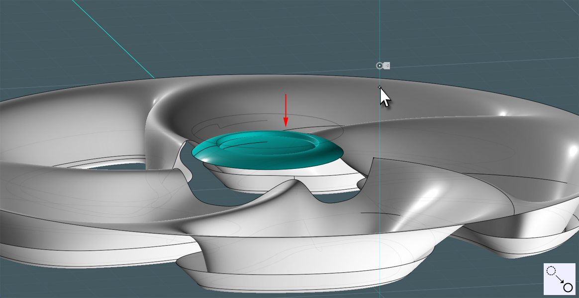
Lower it down to where it will look nice, but keep it somewhat just above the shape's remaining parts.
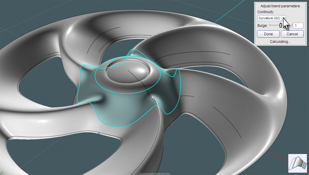
We need to use Blend here, but maybe it would be a good idea to rotate the Revolved shape so that the seams match.
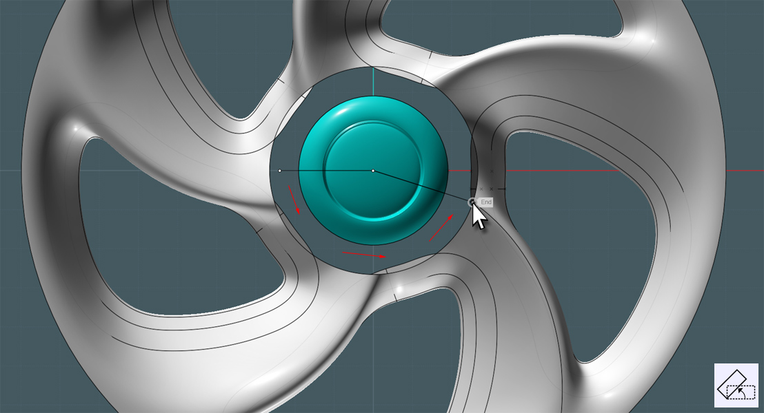
Use a G2 mode Blend between the two edges. NICE HUH!