Hi Curious,
re:
> I am just wondering what is special of the green curves that I used to loft the green model :-)
Nothing really jumps out at me, it would take quite a lot of analysis effort to try and find out the answer.
> Regarding your uploaded file, if I select the entire model I can apply a fillet of as high as 8...17 units
> on it. If I select any of the curves on their own, fillet completely fails (8 or 17).
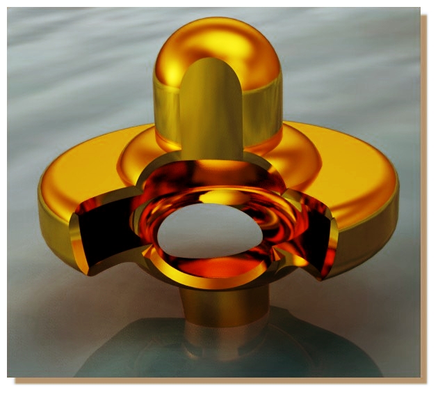
Selecting only some of the edges that come off of a common point instead of all makes the filleting process a little different - it can't build a corner patch and instead has to intersect the fillets with each other and that can be difficult when they are different sizes where they meet up. In that case there the intersection is failing but the fillet pieces are still generated so that you have something to work with and can put them in place using trimming.
If you did want to only fillet some of those edges for the horizontal ones it would be good to do it at this stage before trimming the pieces against each other:

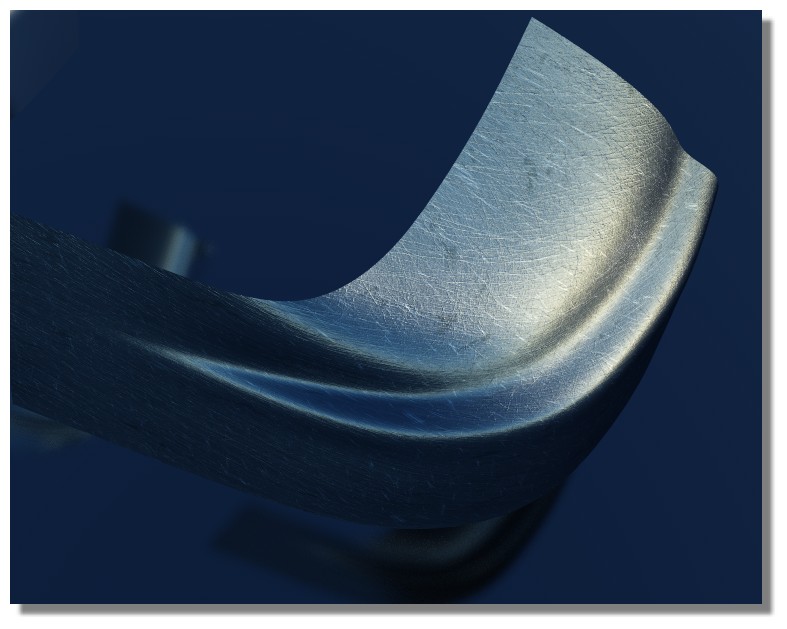
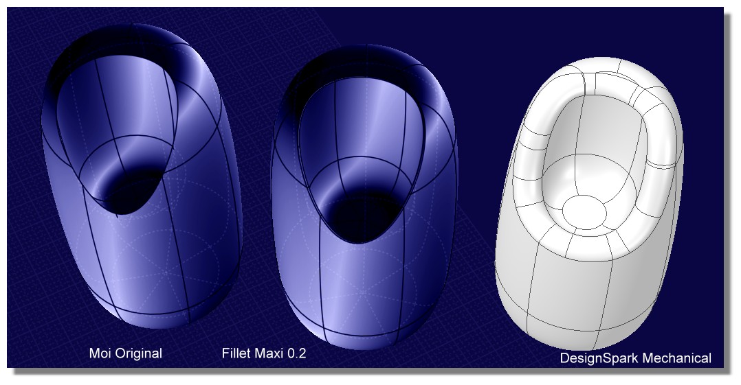
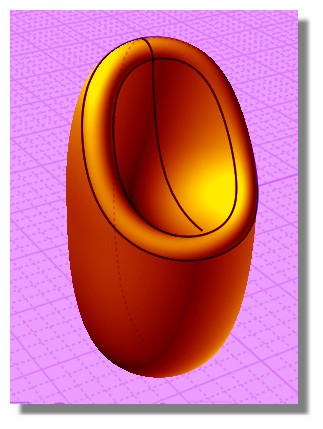
> Plus the surface quality of the fillet in the corner seems not nice in reflections.
Yeah it looks like the corner juncture patch is a little bunched up. Probably a different CAD program with more sophisticated fillets would do ok on that one.
- Michael |