In side view I would draw a curve from the "top floor" to the "bottom floor". Then turn on "Show Points" if you need to adjust the curve.
Then in top view, I would select the curve, turn on Show Points, and manipulate the curve as required to match up with the top & bottom floors.
Create a flat closed profile curve to represent the cross section of the chute and Sweep it along the path curve (Rail) created above. Select the Cap Ends option when using Sweep. Also, change the Sweep Twist: option to Twist:Flat This keeps the profile stabilized with respect to the ground x/y plane. It also helps to first duplicate your profile curve so you can place one at each end of the rail (path) in the proper orientation.
If your chute involves multiple loops, investigate the Helix tool (within the Draw Menu) to create and modify the Rail for your sweep.
If you want tubes rather than open chutes, used two concentric circles (representing the tube ID & OD) as your profile. Also investigate a MoI script called Pipe2. Of course 3D printing a tube is difficult because of the temporary internal supports that would be difficult to remove. So, you can make the tubes using a separate top & bottom section that would need to be joined together after printing. This would require two profile curves and two sweeps along the same rail to produce the the two halves.
After Sweeping you'll have a solid chute which can be selected & exported as a STL file for your 3D printer.
Ed Ferguson
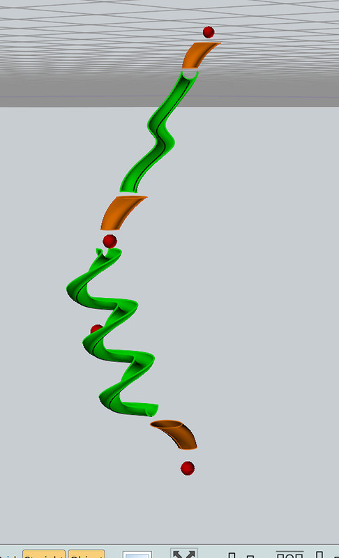
Curved chute above helix chute. Orange objects are short tubes.
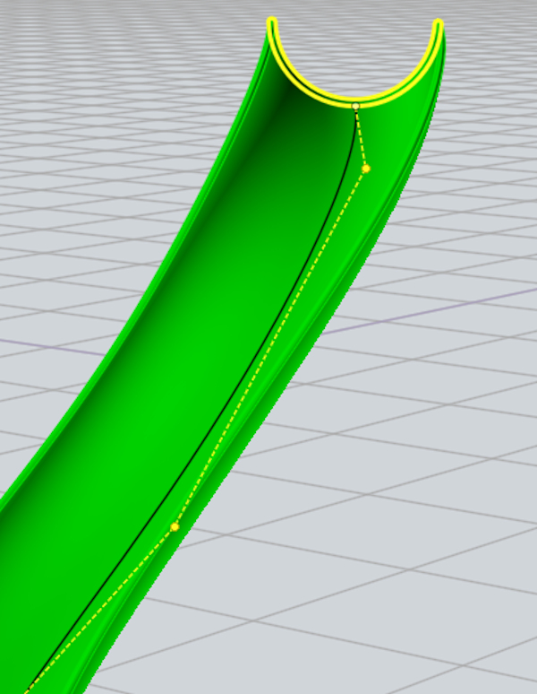
Rail (path) in black with Control Points turned on. Chute profile closed curve highlighted in yellow.
 |


