Booleans causes holes

Next
 From:  Swegmang (ACMS)
8382.1 
Hi, I am still learning moi. I am getting holes after I do Boolean operations at a certain point. I've heard that you cannot fix this which seems to me like a big deal if thats the case.

Any advice on how to deal with this? I uploaded the 3dm file. Try booleaning the main shapes.


I appreciate any help and advice.

  Reply Reply More Options
Post Options
Reply as PM Reply as PM
Print Print
Mark as unread Mark as unread
Relationship Relationship
IP Logged

Previous
Next
 From:  Frenchy Pilou (PILOU)
8382.2 
I don't see problem!
What pieces exactly do you want boolean ?


Normally it's better to have object intersected for make an union boolean!
So add a little cube to each piece to boolean union!
And/or better extrude a internal face ! ;)
All internal faces intersected will be erased during the boolean union!
Better if your principal piece is a "Solid"!

Hide piece for more easy work!

EDITED: 21 Apr 2017 by PILOU

  Reply Reply More Options
Post Options
Reply as PM Reply as PM
Print Print
Mark as unread Mark as unread
Relationship Relationship
IP Logged

Previous
Next
 From:  Michael Gibson
8382.3 In reply to 8382.1 
Hi Swegmang, that will happen if the objects you are booleaning are not closed solids. Normally the booleans figure out which pieces of each object to keep and which to discard based on what solid volume the piece is contained inside of. When your objects are not closed solids that won't be able to happen and it will work as more of a surface trimming operation.

You can tell if an object is a closed solid by the object type indicator, it will read as "Solid" if your object is a closed solid, if it says "Surface" or "Joined srf" it means your object is a surface and not a closed solid volume:


Where did you hear that it's "not fixable" ? Because that's certainly not true, you can build some surfaces and join them in to seal off the holes and make your surface object back into a closed solid again. But it is easier if you keep it as a solid throughout though. You can do that by using solid modeling functions (meaning booleans) to do cutting, don't use surface modeling functions like Edit > Trim and make sure you start out with a solid before you start trying to cut it.

You can also use the script here to highlight unjoined edges (also called "naked edges", that is edges that only belong to one face rather than being joined between 2 faces): http://moi3d.com/forum/index.php?webtag=MOI&msg=2798.6 . That will show you the specific edges that are open.

- Michael
Attachments:

  Reply Reply More Options
Post Options
Reply as PM Reply as PM
Print Print
Mark as unread Mark as unread
Relationship Relationship
IP Logged

Previous
Next
 From:  Michael Gibson
8382.4 In reply to 8382.1 
Also, re:

> Try booleaning the main shapes.

So to answer this specific question - since those 2 main shapes are "joined surfaces" and not closed solids, it doesn't really make sense to boolean them together so don't try doing that. If you want these 2 surface objects to be glued together where their open edges touch each other use the Edit > Join tool for that job, not a boolean.

Booleans are meant for slicing up 2 solids and removing some material. You have neither solids nor do you want any material removed, so a boolean isn't the right tool for that, but Edit > Join is. The Join command only glues naked edges of surfaces together and doesn't try to intersect the objects and remove pieces like the booleans.

Actually though in your particular case you've got another problem yet which is the objects aren't even touching each other, it looks like you've removed a channel between them? There is empty space between them, they would need to at least touch each other in order to be combined:


- Michael

  Reply Reply More Options
Post Options
Reply as PM Reply as PM
Print Print
Mark as unread Mark as unread
Relationship Relationship
IP Logged

Previous
Next
 From:  Swegmang (ACMS)
8382.5 In reply to 8382.4 
Hey everyone thanks so much for the feedback! I really appreciate it.

I still don't understand a lot of the fundamentals but knowing the difference between a solid and joined surface is very helpful!

Sorry for the short reply, but basically I mean, the mesh WAS a solid, and then at a certain point via booleans or some other reason, when I boolean out anything now, the mesh will create a hole, and the boolean no longer keeps the mesh a solid. I want to boolean out a bunch of surface details and extra form changes. The problem is I cannot go any farther now.

I have had this happen with every solid I have worked with, where at some point while I am working booleans break it. I don't have the proper vocabulary to really describe my problem so I am doing my best.

SO I get that I can still boolean, I just want it to stay a solid all the time. And i don't know at what point it breaks or if it's something I'm doing.
I booleaned this cube, I would ideally want this to be a solid. I know the mesh now longer is a solid but I know that people have had this issue, and could I fix this and make it solid again or fix this in the future?

As I said the person I knew said there is nothing you can do about it but I wanted to see what you guys think. He said he saves a lot because of this.


  Reply Reply More Options
Post Options
Reply as PM Reply as PM
Print Print
Mark as unread Mark as unread
Relationship Relationship
IP Logged

Previous
Next
 From:  Michael Gibson
8382.6 In reply to 8382.5 
Hi Swegmang, yes it's possible to repair it but it would be a lot easier if you repaired it right as soon as it became an open surface instead of a closed solid. Don't just continue to do more booleans on the object that isn't a solid because you'll keep on opening more and more holes each of which will need to be filled in order to repair it.

There is a tutorial on object repair techniques here: http://moi3d.com/forum/index.php?webtag=MOI&msg=446.17

To begin with repairing it, first use the select naked edges script that I posted above, it will show you the areas that are open.

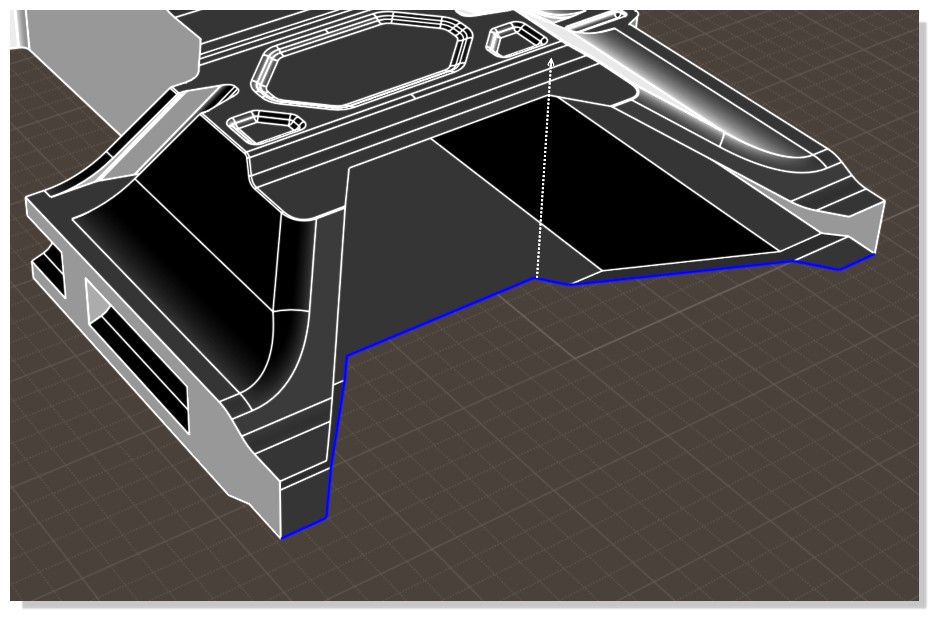
First there is a big hole in the front part:


To repair that, you'll need to re-create the cutting line, you do that by copying these curves down (hold down Ctrl and drag on them) and flattening them (switch to the front view and use the edit frame to do a "flat snap" http://moi3d.com/forum/index.php?webtag=MOI&msg=3378.4 ). Also replace any series of multiple lines that are colinear with one single line:


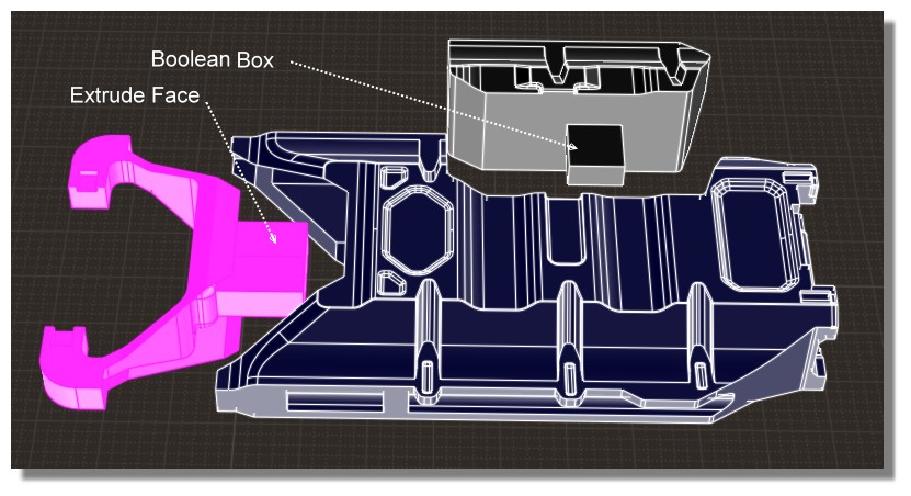
Now that the original 2D planar cutting curve has been restored you can now extrude it up like this:


Now you need to cut the new extrusion with the edges making up the hole, these are the cutting objects:


This will cut the extrusion into 3 pieces, select these outer ones as the pieces to discard:


That will leave you with this trimmed surface:


That's the piece needed to repair the front, select it and the main object and use Edit > Join to glue them together and seal off that hole.

Then there's another area to fix on the opposite side, I'll post about that one next.

- Michael

  Reply Reply More Options
Post Options
Reply as PM Reply as PM
Print Print
Mark as unread Mark as unread
Relationship Relationship
IP Logged

Previous
Next
 From:  Michael Gibson
8382.7 In reply to 8382.5 
Then on the opposite side there are a bunch of naked edges around this filleted area:


It looks like it's these fillets that caused your object to become not solid so that's where the trouble started probably.

See for example these fillets here:


Even though that really looks like 2 fillets with a thin surface between them, that's not what it is - it's actually just 2 fillets with no surface between them, the fillets overshoot past each other by a little bit. So it looks like you used a fillet radius that was just slightly too large to fit in the available space. The fillets were still generated but their ends are not attached to anything.

It would probably be easiest to erase this front protrusion and build it again with a smaller fillet radius. To erase it you can delete all the faces making up that protrusion which will leave a hole, then you can select the edges around the hole and use delete on those too doing an "untrim" (it's covered in that object repair tutorial linked to earlier, also here: http://moi3d.com/forum/index.php?webtag=MOI&msg=444.4) .

That will remove the protrusion so you'll need to rebuild that area:


But now with these steps done your object is back to being a solid and booleans on it should be back to behaving normally again.

I've attached the solid object 3DM file here as repaired_object_3dm.zip .

Hope this helps explain what happened and how it's fixable.

- Michael

  Reply Reply More Options
Post Options
Reply as PM Reply as PM
Print Print
Mark as unread Mark as unread
Relationship Relationship
IP Logged

Previous
Next
 From:  Swegmang (ACMS)
8382.8 In reply to 8382.7 
Thank you SO much Michael, your're the best. I am so glad to know this. I'm too tired to fix it right now but I will definitely start trying to figure this out. I have another model with this issue (or two) I will attempt to fix them as well and if I can't figure it out I will post in here again. I'll lurk some more too before i post:)
Also thanks for more terminology like naked edges, i will try and read more about this.

Again really appreciate the time and awesome answer!
  Reply Reply More Options
Post Options
Reply as PM Reply as PM
Print Print
Mark as unread Mark as unread
Relationship Relationship
IP Logged

Previous
Next
 From:  Frenchy Pilou (PILOU)
8382.9 
Remade all: works fine!

Just a question
What is the use to Flat the "moved lines" and not just vertical extrude the lines bottom not moved?

EDITED: 22 Apr 2017 by PILOU

  Reply Reply More Options
Post Options
Reply as PM Reply as PM
Print Print
Mark as unread Mark as unread
Relationship Relationship
IP Logged

Previous
Next
 From:  Michael Gibson
8382.10 In reply to 8382.9 
Hi Pilou,

re:
> What is the use to Flat the "moved lines" and not just vertical extrude
> the lines bottom not moved?

Flattening it has the added benefit of making the extruded faces able to be handled as analytic plane surfaces which can then get special treatment in things like intersection calculations.

It would also work to extrude the edges directly, it would result though in surfaces that have slanted control points with a parallelogram type shape. It's not like that's horrible but it means they will be generic surfaces and not able to be handled as an analytic plane surface.

So flattening it out just helps to make the end surfaces as simplified as possible.

- Michael
  Reply Reply More Options
Post Options
Reply as PM Reply as PM
Print Print
Mark as unread Mark as unread
Relationship Relationship
IP Logged

Previous
Next
 From:  Frenchy Pilou (PILOU)
8382.11 In reply to 8382.10 
THX for the infos!
---
Pilou
Is beautiful that please without concept!
My Gallery
  Reply Reply More Options
Post Options
Reply as PM Reply as PM
Print Print
Mark as unread Mark as unread
Relationship Relationship
IP Logged

Previous
Next
 From:  Swegmang (ACMS)
8382.12 
I just did this on the first part, and used all the scripts you sent me, thank you so much Michael, you save my life. I really appreciate it. Can't wait to try and fix the other ones!
  Reply Reply More Options
Post Options
Reply as PM Reply as PM
Print Print
Mark as unread Mark as unread
Relationship Relationship
IP Logged

Previous
 From:  Michael Gibson
8382.13 In reply to 8382.12 
You're welcome, I'm glad you're able to continue with your modeling!

- Michael
  Reply Reply More Options
Post Options
Reply as PM Reply as PM
Print Print
Mark as unread Mark as unread
Relationship Relationship
IP Logged
 

Reply to All Reply to All