Boolean difference
 1-20  21-37

Next
 From:  gunter511
8249.1 
Hi,

I'm trying what I thought would be a simple boolean difference but for some reason, it just doesn't happen.


If I draw a straight perpendicular line, it works but not with the one at an angle.

Could someone help please?

Thanks!
Gunter

  Reply Reply More Options
Post Options
Reply as PM Reply as PM
Print Print
Mark as unread Mark as unread
Relationship Relationship
IP Logged

Previous
Next
 From:  Frenchy Pilou (PILOU)
8249.2 
Better to separate line from the volume!
Something like this
(after the boolean Diff one part was moved)


And for have no any problem better to take a plan as Boolean Diff
so extrude your line!


PS Also better if you post your file 3dm !
(an image is not sufficient for avoid misundestanting! :)
And that avoid to sculpt something by the helper! :)

EDITED: 3 Jan 2017 by PILOU

  Reply Reply More Options
Post Options
Reply as PM Reply as PM
Print Print
Mark as unread Mark as unread
Relationship Relationship
IP Logged

Previous
Next
 From:  gunter511
8249.3 In reply to 8249.2 
Thanks Pilou, I've attached the file.

I'm trying to create a recess in the object where I have drawn the line.

Thank you!
Gunter
Attachments:

  Reply Reply More Options
Post Options
Reply as PM Reply as PM
Print Print
Mark as unread Mark as unread
Relationship Relationship
IP Logged

Message 8249.4 deleted 3 Jan 2017 by BEMFARMER

Previous
Next
 From:  amur (STEFAN)
8249.5 
My little test,

Construction, Curve, ISO =V

Circle Profile sweeped around ISO Curve and then a boolean operation.

Regards
Stefan

Attachments:

  Reply Reply More Options
Post Options
Reply as PM Reply as PM
Print Print
Mark as unread Mark as unread
Relationship Relationship
IP Logged

Previous
Next
 From:  gunter511
8249.6 In reply to 8249.5 
Stefan,

What you've done is exactly what I want to do but being the relative newbie that I am, I don't understand your instructions!

Could you please explain?

Many thanks!
Gunter
  Reply Reply More Options
Post Options
Reply as PM Reply as PM
Print Print
Mark as unread Mark as unread
Relationship Relationship
IP Logged

Previous
Next
 From:  Finema
8249.7 In reply to 8249.3 
Hi
Extend your line and apply the boolean

EDITED: 9 May 2020 by FINEMA

  Reply Reply More Options
Post Options
Reply as PM Reply as PM
Print Print
Mark as unread Mark as unread
Relationship Relationship
IP Logged

Previous
Next
 From:  gunter511
8249.8 In reply to 8249.7 
Finema,

Thank you for your reply. It works if the line is perpendicular as under but if it's slanting it donesn't seem to work. I must be doing something wrong.


Thanks!
Gunter

  Reply Reply More Options
Post Options
Reply as PM Reply as PM
Print Print
Mark as unread Mark as unread
Relationship Relationship
IP Logged

Previous
Next
 From:  amur (STEFAN)
8249.9 
Hi Gunter,

you need to go under the "Construct" Menu to the "Curve" Icon and then select the "ISO" Icon with "V" settings only and select in the right view your object and move the yellow ISO curve until it matches (snaps) the position of your outer curve.

After that is done your create a small circle (as profile) for the "Sweep" Command were you use the ISO Curve as rail and then do a boolean subtract, to obtain the engraving.

Hope my explanation is clear enough.

Regards
Stefan
  Reply Reply More Options
Post Options
Reply as PM Reply as PM
Print Print
Mark as unread Mark as unread
Relationship Relationship
IP Logged

Previous
Next
 From:  Finema
8249.10 
I use your line in your 3dm file and it's OK
  Reply Reply More Options
Post Options
Reply as PM Reply as PM
Print Print
Mark as unread Mark as unread
Relationship Relationship
IP Logged

Previous
Next
 From:  gunter511
8249.11 In reply to 8249.9 
Stefan, Thank you that worked perfectly.

Thank you for your help!

Gunter
  Reply Reply More Options
Post Options
Reply as PM Reply as PM
Print Print
Mark as unread Mark as unread
Relationship Relationship
IP Logged

Previous
Next
 From:  Finema
8249.12 In reply to 8249.11 
In fact i haven't understand what you want to do :)
can we show us the result ?
thanks
  Reply Reply More Options
Post Options
Reply as PM Reply as PM
Print Print
Mark as unread Mark as unread
Relationship Relationship
IP Logged

Previous
Next
 From:  Frenchy Pilou (PILOU)
8249.13 
Another time a prove that send the 3dm file is crucial! :)
  Reply Reply More Options
Post Options
Reply as PM Reply as PM
Print Print
Mark as unread Mark as unread
Relationship Relationship
IP Logged

Previous
Next
 From:  amur (STEFAN)
8249.14 
You're welcome Gunter,

glad it worked that way!

Regards
Stefan
  Reply Reply More Options
Post Options
Reply as PM Reply as PM
Print Print
Mark as unread Mark as unread
Relationship Relationship
IP Logged

Previous
Next
 From:  Michael Gibson
8249.15 In reply to 8249.1 
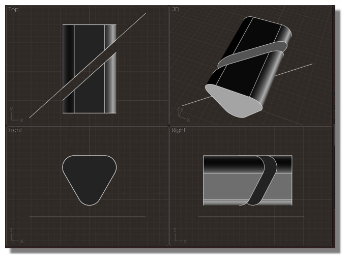
Hi Gunter, so the problem there is that a line that is angled diagonally in 3D space does not have a well defined single extrusion direction.

The boolean will want to extrude the line into a plane and then use the plane to cut the object, but it needs to know what direction it should extrude it. When your line is on one of the world axis planes it will use that axis direction, that's why those other lines worked.

For your situation with a line at an angle not in a world plane like that, you will need to extrude the line into a plane yourself and then use the plane as the cutting object in the boolean. There is a "Set dir" option in the Extrude command that can be used for extruding in a specific direction.

Another way that might work more easily for making an angled cutting plane is drawing it using the Draw solid > Plane > 3 pts command.

- Michael
  Reply Reply More Options
Post Options
Reply as PM Reply as PM
Print Print
Mark as unread Mark as unread
Relationship Relationship
IP Logged

Previous
Next
 From:  gunter511
8249.16 In reply to 8249.15 
Hi Michael,

Thanks for clarifying. Making a plane worked well.

I'm now trying to make two recesses and have tried scaling and sweeping (Stefan's suggestion) but they don't seem to turn out right. I'm looking to create recesses only on the left and right faces, not the bottom of the object.


Thanks in advance!
Gunter

  Reply Reply More Options
Post Options
Reply as PM Reply as PM
Print Print
Mark as unread Mark as unread
Relationship Relationship
IP Logged

Previous
Next
 From:  Frenchy Pilou (PILOU)
8249.17 In reply to 8249.16 
You can make also a simple Sweep 2 Rails! ;)

EDITED: 4 Jan 2017 by PILOU

  Reply Reply More Options
Post Options
Reply as PM Reply as PM
Print Print
Mark as unread Mark as unread
Relationship Relationship
IP Logged

Previous
Next
 From:  gunter511
8249.18 In reply to 8249.17 
Thanks Pilou, I tried that but I'm getting a strange anomaly at the corners.


Gunter

  Reply Reply More Options
Post Options
Reply as PM Reply as PM
Print Print
Mark as unread Mark as unread
Relationship Relationship
IP Logged

Previous
Next
 From:  Finema
8249.19 In reply to 8249.18 
hi
you can add an edge smaller between 2 form (see screen 1)
and do a Loft > Loose Style on the 3 3 edges (see srceen 2)

EDITED: 9 May 2020 by FINEMA

  Reply Reply More Options
Post Options
Reply as PM Reply as PM
Print Print
Mark as unread Mark as unread
Relationship Relationship
IP Logged

Previous
Next
 From:  gunter511
8249.20 In reply to 8249.19 
Thank you Finema, that does work. I scaled the middle edge smaller but now the recess is all around the object rather than only the sides of the triangle which is where I would like them!

Gunter
  Reply Reply More Options
Post Options
Reply as PM Reply as PM
Print Print
Mark as unread Mark as unread
Relationship Relationship
IP Logged
 

Reply to All Reply to All


Show messages:  1-20  21-37