Hi Marco,
> But...i must admit that, although your indications were exhaustive,
> they are doubtless for anyone who's more experienced than me in the nurbs's world.
I mean that when a single line is extruded, it results in a plane surface, and it is represented internally by special type of surface sub-class which can simplify various calculations such as surface/surface intersection.
If you just extrude your original curve that are made up of lines and arcs, you will get these kinds of simple planes in the areas where lines were extruded.
In the case that you're trying to achieve, you will not have that type of structure, there will be just one general surface and it won't be represented by an analytic sub-class.
> I mean.....
>
> As i tried to express in my previous post
> (
http://moi3d.com/forum/index.php?webtag=MOI&msg=7912.3),
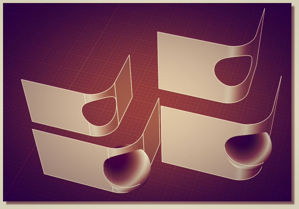
> i thought that, as showed in the attached file example2.3dm and the relative picture,
Ok, but I'm not sure what that picture is illustrating - you've got 2 filleted results there, neither of which is ill formed, there isn't really any reason to consider the one with multiple segments to be worse than the other one...
Going through a bunch of hoops to generate the single surface one is not worth the time unless it solves some particular problem.
> the surfaces obtained without seams, or with the minimum amount of seams,
> are better suited for filleting or boolean operations, for example.
>
> Or that a surface without seam could be better rendered or could present a finer
> surface curvature continuity.
Well, maybe there is some confusion about the term "seams" - normally in NURBS modeling a "seam edge" is a special type of edge, one on a closed surface like a cylinder or sphere surface where opposite sides of the surface come together and touch each other. These can often times be awkward when it comes to filleting, especially for spheres.
But the things you are talking about trying to eliminate here are not "seams", they're just regular edges.
> Is it correct to think that, having less seams in a surface, could lead to be able to
> create things like fillets and blends, without the need of merging the edges ?
This is not automatically true in all cases, it depends on the particular situation.
For something that is made up of structured parts like a line and arc drawing that you are showing here, it is usually better to have a multi-face structure with one separate face for each line and arc, so that each surface can be represented by a plane or cylinder surface sub-class and utilize some more simple code paths.
For your case here, you would only want to eliminate all those edges if you were working around some specific problem, like there happens to be a tiny edge fragment left over after a boolean and that little tiny fragment was making it difficult to do filleting later. But those are things you would do just for the specific case that was causing the problem.
For the most general use case where you've got something structured with straight lines in it, I wouldn't recommend trying to eliminate the segmentation like you're asking about.
When you are doing a boolean with a sphere, that's a case where it can be helpful to position the sphere so the sphere's seam edge won't be sticking out just a tiny bit in the booleaned result.
But just because there are some cases here and there where it could help with avoiding fillet problem does not automatically mean that you should put a ton of effort into removing as many edges as possible on every single operation.
- Michael