Flow as an "unfold tool"
 1-20  21-28

Next
 From:  Mik (MIKULAS)
7406.1 
Hi everyone,

I've tested Flow command as an "unfold tool". Sample file, attached. It seems to be precise way to get planar shape for DXF export which can be used for LASER Cut and CNC press machines.


BUT: Aluminium gives different outer dimensions after bending in comparison to stainless steel for instance; therefore unfolded shape has to be corrected in order to match dimension drawing. Software which can unfold CAD data allows change overall length of unfolded part by using coefficient which change only curved part of model, planar parts of model stay constant, therefore position of cut shape (holes) inside planar parts stay constant as well. This is useful for exporting DXF for different materials.

I've tried to correct unfolded shape via Flow - Stretch with changed length of target curve (line), but this subcommand change planar and "excurved" part of model equally.

Is it possible to add additional checkbox "Stretch radius only" into Flow command which equally change only curved (yellow) part of model? See attached picture, please.


Thanks for comments.

Mik

EDITED: 19 May 2015 by MIKULAS


  Reply Reply More Options
Post Options
Reply as PM Reply as PM
Print Print
Mark as unread Mark as unread
Relationship Relationship
IP Logged

Previous
Next
 From:  Michael Gibson
7406.2 In reply to 7406.1 
Hi Mik, I'm not entirely sure if I understand properly but I think you can get what you want by using Edit > Separate on the pieces that you want to flex, and only using Flow on those pieces and then for the straight ones only use regular rotation to move those around...

There are various CAD programs that have detailed special mechanisms for doing sheet metal design, you will probably be better off using one of those programs for this type of thing rather than Moi which is not designed specifically for sheet metal models.

You might take a look at Geomagic Design (formerly called Alibre Design), I think it has some special sheet metal tools in it, check out the "Sheet Metal Design" section of this page: http://support1.geomagic.com/link/portal/5605/5668/Article/2285/Geomagic-Design-Support-Video-Learning-Center

- Michael
  Reply Reply More Options
Post Options
Reply as PM Reply as PM
Print Print
Mark as unread Mark as unread
Relationship Relationship
IP Logged

Previous
Next
 From:  Frenchy Pilou (PILOU)
7406.3 
SpaceClaim (not Free DesignSpark) has this sort of thing ;) but it's not free!

EDITED: 19 May 2015 by PILOU

  Reply Reply More Options
Post Options
Reply as PM Reply as PM
Print Print
Mark as unread Mark as unread
Relationship Relationship
IP Logged

Previous
Next
 From:  Frenchy Pilou (PILOU)
7406.4 
Seems remember that FormZ free has also an Unfold tool!
But curiously it's not in the list of features :O

Minute 24 . 10

EDITED: 19 May 2015 by PILOU

  Reply Reply More Options
Post Options
Reply as PM Reply as PM
Print Print
Mark as unread Mark as unread
Relationship Relationship
IP Logged

Previous
Next
 From:  Mik (MIKULAS)
7406.5 
Hi,

thanks for comments guys. I know that exists several specialised programs for metal sheet design, but this link http://moi3d.com/forum/index.php?webtag=MOI&msg=4813.4 inspired me to use Flow command for unfold operation of bended simple objects inside MoI and results seems to me very good.

I've modelled simple shape:


then I used Flow command and all dimensions match to unfold planar segments:


Then I tried to unfold model in specialised program for CNC press machine. One DXF was created without any correction and second DXF with correction which correspond to used press tool and metal sheet material and thickness. Correction ensure to get right dimension after bending (in this sample it's 27 mm). DXF comparison is here:


Because it's possible to calculate unfold length of planar shape including correction factor in advance, therefore I've tried to use Flow > Stretch with calculated line as a target curve.
After unfolding the overall length is correct, but length of segments are different:


therefore I'm interested in how it's complicated to add additional feature into Flow command - "Stretch radius only".

I can do it manually of course, but additional checkbox is more elegant and result is quicker.

Unfortunately I'm not programmer.

Mik

  Reply Reply More Options
Post Options
Reply as PM Reply as PM
Print Print
Mark as unread Mark as unread
Relationship Relationship
IP Logged

Previous
Next
 From:  Michael Gibson
7406.6 In reply to 7406.5 
Hi Mik, re: "Stretch radius only" - I guess it's possible but it would be a really special case option that could only be enabled for very specific structures that had separate faces right at the areas where it changed from stretch to non-stretch. It would be bad to try and use it on say one big surface that crossed over the spots that switched from stretch to non-stretch because the deformation function would be discontinuous in those spots. It would likely cause a strange sort of hiccup right at those locations. For example in your case there it looks like the side walls are long surfaces that cross over those zones so those surfaces would be problematic.

So it would require flow to analyze your faces and figure out which pieces were associated with which segments which could be kind of tricky... It would probably be more robust to have a special purpose separate command that would do it, maybe something that did one bend at a time and you selected the bent faces before running the command so it would not have to try and analyze your geometry to find them. I'm not quite sure what would be involved in making that exactly.

- Michael
  Reply Reply More Options
Post Options
Reply as PM Reply as PM
Print Print
Mark as unread Mark as unread
Relationship Relationship
IP Logged

Previous
Next
 From:  Mik (MIKULAS)
7406.7 
Hi Michael,

thank you for reply. You are right that this way of unfold objects is reasonable only for specific structures. Practically for simple models with parallel side walls, which is modelled with specific rule.


I've modelled next test objects and unfold them in AutoPOL (http://www.autopol.com/products/unfolder/introduction/introduction.asp?sidebar=intro_u)
Left object was modelled by loft command, object on right is modelled via extrusion and union.


imported DXF from AutoPOL - 3dm, attached


I wanted to see the difference of unfolding process, detail of bended part of models is here:


Of course I would obtain same results by copy of outer surface of model - rotate axis of separated faces, calculate length of radius, joint together and export DXF.


Question is, if it's possible to write script which can do this operation automatically. Length of radius should be let as variable which take into account material and tooling.

MoI is excellent CAD modeller and construction program and this utility would help a lot for metal sheet parts, which is quite often part of more complex assemblies.

Maybe such scripts will be nice exercise for some experts from this amazing forum.

Here is the test of Cloth script written by Max Smirnov, for instance :-) http://moi3d.com/gallery/viewitem.php?id=790

Mik

  Reply Reply More Options
Post Options
Reply as PM Reply as PM
Print Print
Mark as unread Mark as unread
Relationship Relationship
IP Logged

Previous
Next
 From:  Frenchy Pilou (PILOU)
7406.8 In reply to 7406.7 
The Offset function and UnWrapCurve script can't help you for some actions ?
http://moi3d.com/forum/messages.php?webtag=MOI&msg=5136.1

EDITED: 21 May 2015 by PILOU

  Reply Reply More Options
Post Options
Reply as PM Reply as PM
Print Print
Mark as unread Mark as unread
Relationship Relationship
IP Logged

Previous
Next
 From:  Mik (MIKULAS)
7406.9 
Hi Pilou,

you mean probably rotation faces without drawing auxiliary circles, it means choosing edge as axis of rotation and then offset the face.

Because it's possible to calculate compensated length of radius, maybe it's more handy to rotate the face using centre of radius and then move the face in right direction by calculated distance.

Mik
  Reply Reply More Options
Post Options
Reply as PM Reply as PM
Print Print
Mark as unread Mark as unread
Relationship Relationship
IP Logged

Previous
Next
 From:  Mik (MIKULAS)
7406.10 
Understand you meant Pilou, I didn't see the thread link in your previous post.

Mik
  Reply Reply More Options
Post Options
Reply as PM Reply as PM
Print Print
Mark as unread Mark as unread
Relationship Relationship
IP Logged

Previous
Next
 From:  Michael Gibson
7406.11 In reply to 7406.7 
Hi Mik,

> Question is, if it's possible to write script which can do this operation automatically. Length
> of radius should be let as variable which take into account material and tooling.

I'm not really sure if it's possible with the current stuff that's available to scripts... For example it's difficult for a script to analyze different geometric features of surfaces like find the center point of your bend, there just isn't currently a lot of functionality exposed for scripts to gather that type of information.

In the future I want to enhance the script layer to make more things available for scripts to access, something like this probably would not be feasible until that time.

- Michael
  Reply Reply More Options
Post Options
Reply as PM Reply as PM
Print Print
Mark as unread Mark as unread
Relationship Relationship
IP Logged

Previous
Next
 From:  Frenchy Pilou (PILOU)
7406.12 In reply to 7406.11 
The function Join don't keep multi colors of the curves multicolored joined!
So when you Unwrap a curve "joined" it's monoclor so you can't see the differents extremities! :)
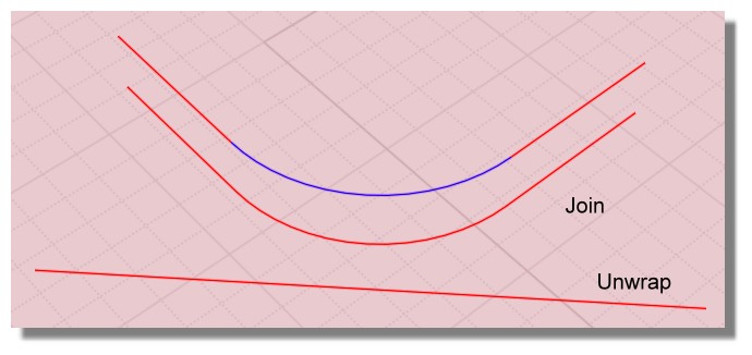


Flow yes! :)
So Flow the curves on their Unwrap! ;)
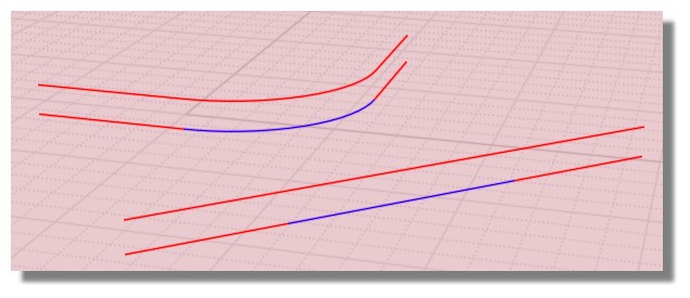
Have you the good result of your Unfold with this method ? Alas seems not!


script:/* Past Calculate lenght of selected curves inside the clipboard */ var crvs = moi.geometryDatabase.getSelectedObjects().getCurves(); var len = 0.0; for ( var i = 0; i < crvs.length; ++i ) len += crvs.item(i).getLength(); moi.copyTextToClipboard( len );

Seems the blue unfolded by Flow is not exactly the same or this tolerance is sufficient?
7,8539 8162216791 Blue Curve
7,8539 5062752401 Blue Unfolded by Flow

7,8539 8162216791 Unwraped is perfect!

So seems better use some Unwrap "unfold" method than Flow "unfold" method! :)

When you try Flow on the same place of some curves you can name them before then over put them
Select them with the Browser / Call the function Flow / Hide origin curve / Point the Base Curve etc...
Alas that change not the relative bad result of the Flow method! :)

EDITED: 21 May 2015 by PILOU

  Reply Reply More Options
Post Options
Reply as PM Reply as PM
Print Print
Mark as unread Mark as unread
Relationship Relationship
IP Logged

Previous
Next
 From:  Mik (MIKULAS)
7406.13 In reply to 7406.11 
Hi Michael,

OK, understand, don't worry and thank you for your time.

Mik
  Reply Reply More Options
Post Options
Reply as PM Reply as PM
Print Print
Mark as unread Mark as unread
Relationship Relationship
IP Logged

Previous
Next
 From:  Mik (MIKULAS)
7406.14 In reply to 7406.12 
Hi Pilou,
many thanks for your reply. I'm not sure, but I think that I do the similar thing. When I prepare geometry to Flow - "Unfold" process I highlight edges of part profile first, then I use Offset command to take Base curve which goes in the middle of material thickness. Offset curve is Joined automatically. This curve I Unwrap as a target curve. After that I highlight part (solid), point the Base Curve, then Target curve and then I obtain planar solid. If I color faces before Flow, so result is planar solid with coloured faces. Each unfolded face correspond to original.

I've tried to use your script but I'm not sure if I use it correctly. I choose some curve run the script by shortcut and in clipboard is saved length of selected curve.

May I ask you for explanation in more details, please.
Thanks a lot.

Mik
  Reply Reply More Options
Post Options
Reply as PM Reply as PM
Print Print
Mark as unread Mark as unread
Relationship Relationship
IP Logged

Previous
Next
 From:  Frenchy Pilou (PILOU)
7406.15 In reply to 7406.14 
<<< I choose some curve run the script by shortcut and in clipboard is saved length of selected curve.

Yes it's exactly this! :)
The value of the lenght of any curve(s) selected is pasted in the ClipBoard!
So if you have some NotPad open somewhere you can read it after copy the clipBoard inside! :)
Not very speedy but better than nothing! And very informative! :)

Another thing is existing! (maybe not very adapted to your case but...
CurveLengthBeingDrawn :)
http://kyticka.webzdarma.cz/3d/moi/#CurveLengthBeingDrawn

or on my page in French ;)
http://moiscript.weebly.com/curvelengthbeingdrawn.html

EDITED: 22 May 2015 by PILOU

  Reply Reply More Options
Post Options
Reply as PM Reply as PM
Print Print
Mark as unread Mark as unread
Relationship Relationship
IP Logged

Previous
Next
 From:  archetype (FABIENF)
7406.16 
That's an interesting script there, Pilou! I somehow missed that before.

Any idea if this can work during the editing of a curve as well?

Might be useful when trying to keep the length 'constant' while reshaping the curve by its points.

Thanks.
  Reply Reply More Options
Post Options
Reply as PM Reply as PM
Print Print
Mark as unread Mark as unread
Relationship Relationship
IP Logged

Previous
Next
 From:  Frenchy Pilou (PILOU)
7406.17 In reply to 7406.16 
<< Any idea if this can work during the editing of a curve as well?

Alas not with this version!
---
Pilou
Is beautiful that please without concept!
My Gallery
  Reply Reply More Options
Post Options
Reply as PM Reply as PM
Print Print
Mark as unread Mark as unread
Relationship Relationship
IP Logged

Previous
Next
 From:  3dcnc
7406.18 
There are plenty of unfold software tools. I would look at this one at it opens Rhino / Moi 3dm files . Its very clever, as it takes material thickness into account.


http://laminadesign.com/
Image Attachments:
Size: 38.6 KB, Downloaded: 64 times, Dimensions: 560x420px
Size: 32.8 KB, Downloaded: 55 times, Dimensions: 560x420px
  Reply Reply More Options
Post Options
Reply as PM Reply as PM
Print Print
Mark as unread Mark as unread
Relationship Relationship
IP Logged

Previous
Next
 From:  Frenchy Pilou (PILOU)
7406.19 In reply to 7406.18 
Not sure that it developps object as volume result ? Only as surface ...

EDITED: 23 May 2015 by PILOU

  Reply Reply More Options
Post Options
Reply as PM Reply as PM
Print Print
Mark as unread Mark as unread
Relationship Relationship
IP Logged

Previous
Next
 From:  Ditto
7406.20 In reply to 7406.19 
>> Not sure that it developps object as volume result ? Only as surface ...

Frenchy: Yes, the result is a surface, but this surface is calculated depending on the material and the material thickness to unroll. Let me cite the manual:

<snip>
Material: Use the "Material" menu to select the material (e.g. paper, steel, PETG) and material thickness to use. Lamina will take your material and its thickness into account when designing the 2-D cut path, to assure a proper fit of all the final pieces
</snip>
  Reply Reply More Options
Post Options
Reply as PM Reply as PM
Print Print
Mark as unread Mark as unread
Relationship Relationship
IP Logged
 

Reply to All Reply to All


Show messages:  1-20  21-28