Modeling exercice...
 1-20  21-40  41

Next
 From:  Finema
7196.1 
Hello,

By way of exercise, and especially to perfect me, I try to model a rather complex decanter.
I thus began to put the plans in bottom and to draw main lines.
But at the time of creating "petals", impossible to find the "technique" most squeaky clean to realize that.
I just ask you how you would make to model this thing.
Ps: I tried Projections, Boolean, Cuts, etc. but in vain.
Thank you.

EDITED: 9 May 2020 by FINEMA

  Reply Reply More Options
Post Options
Reply as PM Reply as PM
Print Print
Mark as unread Mark as unread
Relationship Relationship
IP Logged

Previous
Next
 From:  Michael Gibson
7196.2 In reply to 7196.1 
Hi Finema - complex organic shapes with localized bumps and ripples in them can tend to be difficult to construct in a CAD package. A sculpting type program like 3D Coat or ZBrush would most likely be better suited for a model that has those kinds of qualities in them like your target shape here has. In those programs you run brush strokes over parts of the model and each stroke can have a shaping effect like slightly raising or lowering that area. It's a good method for producing raised and lowered local area details.

So that's my best advice, you would probably be better off using a program that was more specifically targeted at making organic shapes rather than a CAD program which is focused more on broader surfaces defined by profile curves.

If you did want to try and construct it in MoI, it's going to be an advanced project maybe making use of a lot of profile curves arranged in a radial pattern and then using Construct > Loft with the "Loft style = loose" option. That method can be used as a way for doing some kinds of organic shapes (but again like I wrote above an actual organic targeted program will be better suited overall). There are some examples of that method here:

http://moi3d.com/forum/index.php?webtag=MOI&msg=6058.1
http://moi3d.com/forum/index.php?webtag=MOI&msg=6639.2

The other approach would be to try and make surfaces that kind of scoop out chunks of the object and do booleans. But it will be difficult to arrange so many scooped out portions right next to each other as this design has, it sounds like you've already tried this method.

- Michael
  Reply Reply More Options
Post Options
Reply as PM Reply as PM
Print Print
Mark as unread Mark as unread
Relationship Relationship
IP Logged

Previous
Next
 From:  Finema
7196.3 In reply to 7196.2 
Thanks Michael.
Actually, i'm testing MoI, cause I would like to use it all the days in my job and propose it to my business manager.
It's the raison why i'm trying to modeling this kind of decanter.
I'm working on C4D. It's a good polygonal application but too heavy and complicate and the polygonal files are not real file to produce professional product. (manufacturer want IGES).
Really, i will be happy if i found a method to realize this form on MoI.
I have seen the tutorial with wheel or tire and it's perhaps a way.
Thanks again.
  Reply Reply More Options
Post Options
Reply as PM Reply as PM
Print Print
Mark as unread Mark as unread
Relationship Relationship
IP Logged

Previous
Next
 From:  Michael Gibson
7196.4 In reply to 7196.3 
Hi Finema - one possible route to get an IGES result would be to model it in polygons and then use the T-splines plug-in for Rhino to convert from a sub-d surface into NURBS surfaces which can then be exported to IGES.

It's difficult to create organic shaped bumps and lumpy forms in CAD programs, CAD programs are just more focused on precision profile curve driven shapes and such lumpy areas do not fit with the CAD toolset very well.

- Michael
  Reply Reply More Options
Post Options
Reply as PM Reply as PM
Print Print
Mark as unread Mark as unread
Relationship Relationship
IP Logged

Previous
Next
 From:  Finema
7196.5 In reply to 7196.4 
But i can't buy Rhino just in order to convert into Nurbs.
And also, with my little tests, i'm prefer modeling into MoI than C4D.
Are you sure T-Splines plug-in convert very well complex form ? Just remind, in my work, i must sending professional IGES to the manufacturer.
Thanks Michael.
  Reply Reply More Options
Post Options
Reply as PM Reply as PM
Print Print
Mark as unread Mark as unread
Relationship Relationship
IP Logged

Previous
Next
 From:  blowlamp
7196.6 
I did a very quick thing with the 3d Rail Revolve that might be a basis of something for you to try.


Martin.


Attachments:

  Reply Reply More Options
Post Options
Reply as PM Reply as PM
Print Print
Mark as unread Mark as unread
Relationship Relationship
IP Logged

Previous
Next
 From:  Finema
7196.7 In reply to 7196.6 
thanks, but it's difficult to apply this on the bottle plan.
  Reply Reply More Options
Post Options
Reply as PM Reply as PM
Print Print
Mark as unread Mark as unread
Relationship Relationship
IP Logged

Previous
Next
 From:  chrisd (CHRIS_DORDONI)
7196.8 In reply to 7196.5 
Max Smirnov has been working on a subd converter for Moi, go here http://moi3d.com/forum/index.php?webtag=MOI&msg=6674.68

Subd modeling for nurbs is now becoming available in several applications. I believe the new ViaCAD Pro (less expensive than Rhino with T-Splines), as well as FormZ have this ability now.

Also check out Resurf3d, they have a stand alone converter that will take an OBJ with quads and convert it to a smooth IGS surface and its only $80, but you can't edit the shape of the subd in the converter, you would have to go back to your poly modeler. Not as ideal workflow, but less expensive.

EDITED: 24 Jan 2015 by CHRIS_DORDONI

  Reply Reply More Options
Post Options
Reply as PM Reply as PM
Print Print
Mark as unread Mark as unread
Relationship Relationship
IP Logged

Previous
Next
 From:  Finema
7196.9 In reply to 7196.8 
thanks chrisd

i've put the 2 files into command folder of MoI but i dunno how to call this command and how i can use it ?
  Reply Reply More Options
Post Options
Reply as PM Reply as PM
Print Print
Mark as unread Mark as unread
Relationship Relationship
IP Logged

Previous
Next
 From:  chrisd (CHRIS_DORDONI)
7196.10 In reply to 7196.9 
hi Finema,

Actually, I don't own Moi yet, I've been following it closely here. I'm sure someone here can help you that. You could try posting in that thread relating to the script.
  Reply Reply More Options
Post Options
Reply as PM Reply as PM
Print Print
Mark as unread Mark as unread
Relationship Relationship
IP Logged

Previous
Next
 From:  Finema
7196.11 In reply to 7196.10 
ok i found how to use this command but don't match with complex form...
subdiv_beta have just a good job with simple polygonal form
  Reply Reply More Options
Post Options
Reply as PM Reply as PM
Print Print
Mark as unread Mark as unread
Relationship Relationship
IP Logged

Previous
Next
 From:  Michael Gibson
7196.12 In reply to 7196.5 
Hi Finema,

> Are you sure T-Splines plug-in convert very well complex form ? Just remind, in my work, i
> must sending professional IGES to the manufacturer.

I've seen some examples of complex jewelry pieces that were successfully converted to IGES so I think it can work well for that.

It may be a good method to test out anyway if you want to construct things in a sub-d modeling program and then convert to NURBS surfaces (in IGES or STEP format) at the end to transfer to CAD.

- Michael
  Reply Reply More Options
Post Options
Reply as PM Reply as PM
Print Print
Mark as unread Mark as unread
Relationship Relationship
IP Logged

Previous
Next
 From:  OSTexo
7196.13 
Hello,

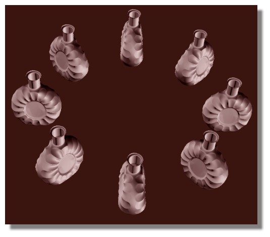
Looking at this a bit I think I would use the existing plans petal edges, determine the depth of the petal at a few places and then make sure I started the petal closer to the front center of the bottle and Sweep the curve past the outside of the front center bottle edge. I'd then use Sweep to get the actual surfaces.This would get me the cutter stamp of the bottle. The last operations would be the easier ones (on second thought, everything looks difficult on this model), I think the XO bottle doesn't actually have a scalloped center, it just looks that way because the (chamfered?) ellipse is Booleaned from the inside of the bottle. The same on the outside, that is why it would be important to actually send the petal surfaces past the edge of the bottle, I don't think the outside profile is actually straight, it looks like you would need to develop a second curve set to Merge and make the solid. You'd be left with some hard edges which would require some filleting work. The bottle looks symmetrical, so you can Mirror the item. It's almost as if you could create the petals as an object to Boolean, then create the bottle and cut that petal stamp away from the bottle. Either way there is nothing simple about the project. Another option is to have a bottle scanned and then use that for the surfacing reference for something like Autodesk Shape Modeling or Tsplines.
  Reply Reply More Options
Post Options
Reply as PM Reply as PM
Print Print
Mark as unread Mark as unread
Relationship Relationship
IP Logged

Previous
Next
 From:  Finema
7196.14 In reply to 7196.12 
Michael,
I have construct the bottle in sub-modeling. Perhaps somebody on the forum, could convert this file into Nurbs ?
  Reply Reply More Options
Post Options
Reply as PM Reply as PM
Print Print
Mark as unread Mark as unread
Relationship Relationship
IP Logged

Previous
Next
 From:  Finema
7196.15 In reply to 7196.13 
Hi OSTexo,

I understand the idea but very hard in practical. I've tested a lot of things but never i've finish because i through it wasn't the right way to process.

Thanks
  Reply Reply More Options
Post Options
Reply as PM Reply as PM
Print Print
Mark as unread Mark as unread
Relationship Relationship
IP Logged

Previous
Next
 From:  OSTexo
7196.16 
Hello Finema,

Is it possible to post the file, in whole or part? Also have you or your vendor considered STEP as a format? Sometimes IGES can require post processing for some surfaces.
  Reply Reply More Options
Post Options
Reply as PM Reply as PM
Print Print
Mark as unread Mark as unread
Relationship Relationship
IP Logged

Previous
Next
 From:  Frenchy Pilou (PILOU)
7196.17 
I just remember that you can use Fusion 360° for free as personal use
http://fusion360.autodesk.com/pricing and press "Do I qualify for free use ?"
You can directly have TSpline to Nurbs...so export to Moi or ...


But I believe that possible in Moi with something like this! :)

EDITED: 25 Jan 2015 by PILOU

  Reply Reply More Options
Post Options
Reply as PM Reply as PM
Print Print
Mark as unread Mark as unread
Relationship Relationship
IP Logged

Previous
Next
 From:  Finema
7196.18 In reply to 7196.17 
Hi Pilou,

1• I've tried Fusion 360 and YES I've convert my .obj into IGES and Open in MoI. (in attachment the Xo decanter in .IGS)

2• Unfortunately,I prefer to realize this form directly in MoI.

Thanks.

EDITED: 28 Jul 2018 by FINEMA

  Reply Reply More Options
Post Options
Reply as PM Reply as PM
Print Print
Mark as unread Mark as unread
Relationship Relationship
IP Logged

Previous
Next
 From:  Frenchy Pilou (PILOU)
7196.19 In reply to 7196.18 
Excellent!

I believe that you can with MOi as I show you above, if you draw the all the edges (with the good form bottom + bottle neck) then Sweep, network, joint, ... them!
You have now the model for do it! :)

EDITED: 26 Jan 2015 by PILOU

  Reply Reply More Options
Post Options
Reply as PM Reply as PM
Print Print
Mark as unread Mark as unread
Relationship Relationship
IP Logged

Previous
Next
 From:  Michael Gibson
7196.20 In reply to 7196.18 
Hi Finema, it looks like the Fusion 360 conversion worked well!

> 2• Unfortunately,I prefer to realize this form directly in MoI.

What is it that you're looking to gain by modeling this in MoI?

MoI is probably not the right tool for this particular kind of a job - MoI is more focused on constructing objects from 2D profile curves. That works great for a lot of mechanical objects, but organic shapes with lumpy bumpy areas are not a good fit for that type of workflow.

Things with lumps and bumps tend to be better accomplished using the organic modeling toolsets which polygon modeling programs are heavily focused on. They focus more on a sculpting type approach pushing and pulling parts of the model around, it's pretty different from the profile curve method that MoI is based on.

The overall modeling mechanisms used in polygon modeling just tends to work better for jobs like this.

Different kinds of models tend to be suited for different kinds of modeling mechanisms - the type of mechanism that MoI is based on works really well for certain kinds of objects, and not so well for other kinds of objects. It's best to use MoI for the projects that it is suited for, and to use different tools for projects that they are better suited for.

- Michael
  Reply Reply More Options
Post Options
Reply as PM Reply as PM
Print Print
Mark as unread Mark as unread
Relationship Relationship
IP Logged
 

Reply to All Reply to All


Show messages:  1-20  21-40  41