Thoughts about Flow
All  1-5  6-18

Previous
Next
 From:  Michael Gibson
6991.6 In reply to 6991.5 
Hi Heiner, if you're having what looks like randomness in the result it's most likely the result of clicking in slightly different areas on each surface on each run-through. For example make sure not to click right exactly on a corner of the surface, because what is actually targeted is an edge and if you click right on a corner it's pretty ambiguous which particular surface edge actually gets targeted.

Can you please post the 3DM model file that is giving you the random-like flow behavior? I will take a look at it and then maybe be able to give you some more specific advice on where to click on it to control it better.

I have thought some about trying to rework the Flow command to be easier to understand. It's somewhat difficult because it can be used in a lot of different ways.

- Michael
  Reply Reply More Options
Post Options
Reply as PM Reply as PM
Print Print
Mark as unread Mark as unread
Relationship Relationship
IP Logged

Previous
Next
 From:  Heiner (BILDERMENSCH)
6991.7 In reply to 6991.6 
Hi Michael,
I attached a file which includes a real shape. Its a real part of my project. The form which is oriented diagonaly is
the one which should be projected onto the U-shaped red planar object. Idealy it would be possible to indicate
where the object starts. In general the orientation in the scene is correct.
Best regards
Heiner

  Reply Reply More Options
Post Options
Reply as PM Reply as PM
Print Print
Mark as unread Mark as unread
Relationship Relationship
IP Logged

Previous
Next
 From:  Michael Gibson
6991.8 In reply to 6991.7 
Hi Heiner - thanks for including the object. That may be a bit difficult to get a good result due to some of the tight bends in your target shape, but here's how you would control it:

First, it's best if the base surface is a simple plane, rather than a surface that just happens to be flat but has some internal warping to it as will happen if you have done a network or a loft between various bent curves. It seems that you have the latter type of surface as your base plane currently, this is probably the source of much of your problems. Here I've drawn in a base plane (the blue one) using Draw solid > Plane > 3 pts:


If you load the attached 3DM file and select the blue plane in it and then turn on its control points using Edit > Show pts, you'll see it is a very simple structure with just 4 control points at the corners. If you do the same to your base plane you should see that it's much more complex with a lot of points it making up, and the surface is kind of internally bent at the corner areas - bending laterally I mean even though it is all flat. The layout of the base plane's control point grid will have a big impact on how Flow works so it's not good to have that kind of surface as your base surface.

Once you have a basic plane as your base surface it will probably help you out a lot - because it's all bent internally it's not so easy to know where the corners of your surface were actually at. With the simple 4 point plane it's a lot easier to know where the 4 corners of the actual surface are located at.

Then to do the Flow, select your object to be deformed (and have only it selected, don't have the base plane or target surface selected yet) then run Transform > Deform > Flow. At the first prompt that says to select the base curve or surface, click on the blue plane and make sure to click on it in one of these 8 point zones, each of which are along an edge towards one side of the edge, but not right at the corner:


You can click on whichever of these 8 points is most convenient, for example I'd suggest clicking on the upper right one like right here:


Then at the next prompt to click on the target surface, there are again 8 zones on the target surface that you want to click on - you will be controlling how the 2 surfaces map to one another by this association. So for this example since we clicked on the upper right one, you want to click on the upper right zone of the target surface, meaning in this location here:


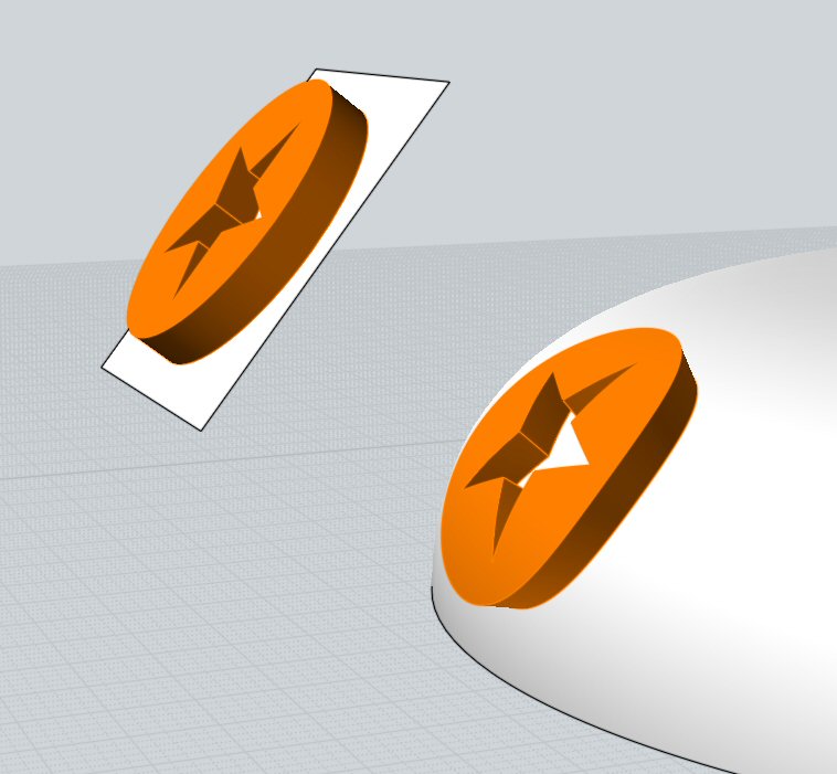
That will be telling Flow to match the top right of the base plane to the top right of the target surface. That will produce this kind of result here:


If that's the wrong side of the surface then there is an additional control on the final Flow stage that you can enable to correct that, that's the "Flip surface normal" checkbox here, when activated it will flip the flow result to the opposite side of the surface normal direction:


I hope that helps to clarify how you'd control Flow for this particular case.

One other note - depending on how the target surface is constructed it can be possible for the result to be sensitive to the control point spacing of the target surface, like if the surface was constructed from an extrusion and the control points in the curve that was extruded had some different spacing along the curve the flow result can stretch or squish along with those changes in spacing. You can help to reduce this by running the Rebuild command on the curve before extruding it, or using the "Refit" option in Loft if you're generating it with Loft.

- Michael

  Reply Reply More Options
Post Options
Reply as PM Reply as PM
Print Print
Mark as unread Mark as unread
Relationship Relationship
IP Logged

Previous
Next
 From:  Heiner (BILDERMENSCH)
6991.9 In reply to 6991.8 
Michael, Wow,
thats all I can say! You really nailed it and from what I can see its exactly what I need!
Thanks for helping me on this. I will try the indicated process as soon as possible and let you
know how it works for me!
Best regards
and two thumbs up for your help!
Heiner
  Reply Reply More Options
Post Options
Reply as PM Reply as PM
Print Print
Mark as unread Mark as unread
Relationship Relationship
IP Logged

Previous
Next
 From:  Heiner (BILDERMENSCH)
6991.10 
Hi Michael,
i took the time and started with the next part out of a series i have to do, and applied carefully your instructions,
down to the controlpoint level. I even had the reconstruct command run over the surface, i use as projection target for flow


Following your instructions and clicking the upper right corner and the corrosponding spot on the surface to project on, i get this result:


No matter which spot I click, i get a very similar result all the time.
If i reorient my source object (the one which i want to do the flow) the results vary and sometimes get closer to the desired result, but
always not entitely. As example please see this:


I will add the file in the next post.
Best regards
Heiner


  Reply Reply More Options
Post Options
Reply as PM Reply as PM
Print Print
Mark as unread Mark as unread
Relationship Relationship
IP Logged

Previous
Next
 From:  Heiner (BILDERMENSCH)
6991.11 
So,
and here is the file in question!
Regards
Heiner

  Reply Reply More Options
Post Options
Reply as PM Reply as PM
Print Print
Mark as unread Mark as unread
Relationship Relationship
IP Logged

Previous
Next
 From:  bemfarmer
6991.12 In reply to 6991.11 
I will suggest running FLIP on the curved target surface.

- Brian

You have nice color Styles!
Image Attachments:
Size: 53.6 KB, Downloaded: 11 times, Dimensions: 161x195px
  Reply Reply More Options
Post Options
Reply as PM Reply as PM
Print Print
Mark as unread Mark as unread
Relationship Relationship
IP Logged

Previous
Next
 From:  Heiner (BILDERMENSCH)
6991.13 In reply to 6991.12 
Hi Brian,
did you get that result using my file?
I tried that, used Flip on the projection surface, and what i got is this:


Almost the same what i had before ... :-(
Regards
Heiner
Attachments:

  Reply Reply More Options
Post Options
Reply as PM Reply as PM
Print Print
Mark as unread Mark as unread
Relationship Relationship
IP Logged

Previous
Next
 From:  bemfarmer
6991.14 In reply to 6991.13 
Hi Heiner

Yes, I used your model.

Either do FLIP once on the Base Surface, or else do FLIP once on the Target Surface.

Run FLOW. I am just selecting somewhere in the surface, not corner points. For the Object to flow, I selected the side of the "seat."

- Brian

(I did manage once to flow the seat sideways once.)

EDITED: 31 Oct 2014 by BEMFARMER

  Reply Reply More Options
Post Options
Reply as PM Reply as PM
Print Print
Mark as unread Mark as unread
Relationship Relationship
IP Logged

Previous
Next
 From:  bemfarmer
6991.15 
.

EDITED: 31 Oct 2014 by BEMFARMER

  Reply Reply More Options
Post Options
Reply as PM Reply as PM
Print Print
Mark as unread Mark as unread
Relationship Relationship
IP Logged

Previous
Next
 From:  Michael Gibson
6991.16 In reply to 6991.10 
Hi Heiner, it looks like the problem in your case there is that you've probably enabled the "Projective" option for Flow, which is a checkbox that shows up in the pick target object stage, here:


In order for your case to work properly and to follow along with the steps I had earlier, make sure that checkbox is unchecked. If it is checked then that will enable a different mode for Flow which is called projective mode, and in projective mode it is expected that every ray that shoots out from the base plane should intersect the target object which is not the kind of arrangement you have.

Projective mode is more for beaming on a small shape onto a local area of an object, rather than stretching it all the way across a target surface. For your case here you want the regular "full stretch across surfaces" method so you will want that checkbox turned off. It is off by default for the start of a program session however if you have enabled it during some previous test of using Flow within this same modeling session it will remember the previous state and so that's probably how you ended up with it turned on.

Anyway, if you uncheck that option you should be able to get things to work as in those previously described steps.

- Michael

  Reply Reply More Options
Post Options
Reply as PM Reply as PM
Print Print
Mark as unread Mark as unread
Relationship Relationship
IP Logged

Previous
Next
 From:  Michael Gibson
6991.17 In reply to 6991.13 
Hi Heiner, so just as a bit more description of "Projective" mode, the way Flow works with that option enabled is that it shoots out rays from the base plane which in your case results in rays like this:


It is expecting those rays to intersect the target object. But as you can see here there are a large number of rays that do not intersect your target object. In places that do not intersect there will be a kind of default transformation set up, it can tolerate a small number of missed rays but not big broad areas where there are not any ray intersections.

So your case here is not a good candidate for the "Projective" flow mode, you need to use the regular non-projective mode so make sure the Projective checkbox is turned off.

Projective mode works well when you want to place a small object onto a localized area of a larger object something more like this:


- Michael

  Reply Reply More Options
Post Options
Reply as PM Reply as PM
Print Print
Mark as unread Mark as unread
Relationship Relationship
IP Logged

Previous
 From:  Heiner (BILDERMENSCH)
6991.18 In reply to 6991.17 
Hmmm, it seems as if my understandig of "projection" was entirely wrong ...
I have it working now, thanks to you!
Best Regards
Heiner
  Reply Reply More Options
Post Options
Reply as PM Reply as PM
Print Print
Mark as unread Mark as unread
Relationship Relationship
IP Logged
 

Reply to All Reply to All


Show messages: All  1-5  6-18