Spiral Bevel Gear and Pinion

Next
 From:  bemfarmer
6763.1 
A person on the Geomagic forum (Alibre) began a spiral bevel pinion, using tooth profile generated from an excel file (pinion Macros) from here:
http://www.spiralbevel.com

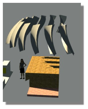
I completed the 8 remaining Boolean difference cutouts using MoI here:

http://forum.alibre.com/viewtopic.php?f=10&t=17393&p=109577#p109577

The tooth profile cutout for the matching gear is also generate-able from the excel file, also by using the gear Macros.
It remains to draw up a gear blank, and Boolean difference away the 20 tooth cutouts.

I used excel 2010, and had to enable the Developer tab, and enable the Macros. (They should be disabled afterwards for security.)

The spreadsheet is protected from entering other gear ratios (tooth numbers).
Other tooth numbers generate different tooth shapes.
(The basic program costs the same as MoI. Tooth Contact Analysis costs more.)
I would expect that the purchased program is more advanced. (?)
The professional gears are manufactured with CNC machines.

The two Macros generate the IGES tooth cutout files, which MoI can import.
The Macros code is password protected, copyrighted, and is fairly lengthy.

There is also a Crown Gear (= face gear) excel spreadsheet demo.

- Brian


EDITED: 13 Jun 2014 by BEMFARMER

Attachments:

  Reply Reply More Options
Post Options
Reply as PM Reply as PM
Print Print
Mark as unread Mark as unread
Relationship Relationship
IP Logged

Previous
Next
 From:  Michael Gibson
6763.2 In reply to 6763.1 
Wow cool, that's some pretty fancy stuff in Excel!

- Michael
  Reply Reply More Options
Post Options
Reply as PM Reply as PM
Print Print
Mark as unread Mark as unread
Relationship Relationship
IP Logged

Previous
Next
 From:  Frenchy Pilou (PILOU)
6763.3 
Do you will adapt this on a Script for Moi ?

EDITED: 13 Jun 2014 by PILOU

  Reply Reply More Options
Post Options
Reply as PM Reply as PM
Print Print
Mark as unread Mark as unread
Relationship Relationship
IP Logged

Previous
Next
 From:  Mike (MGG942)
6763.4 In reply to 6763.1 
Oooh! How enticing. But something I'll have to look forward to when I've mastered some more of the basics.
  Reply Reply More Options
Post Options
Reply as PM Reply as PM
Print Print
Mark as unread Mark as unread
Relationship Relationship
IP Logged

Previous
Next
 From:  bemfarmer
6763.5 In reply to 6763.3 
I might try for a script. It would be for "illustrative purposes," or safe hobby use only, not for building helicopters. :-)
It seems like gear making is an art. They do heat treatment, tooth contact analysis and more grinding...
I'm still trying to draw up the gear blank. The face tangents appear to join at a different point than the "gear heel pitch diameters."
The blank should be the same as for regular bevel gears...

The crown gear is said to have advantages over the spiral bevel gear, strength and easier alignment.

The globoid worm gear looks interesting also. The pinion is said to be easily drawn in CAD. The gear is said to be very complex, but
maybe a bunch of sequential Booleans with the pinion would work for amateur use?

- Brian
  Reply Reply More Options
Post Options
Reply as PM Reply as PM
Print Print
Mark as unread Mark as unread
Relationship Relationship
IP Logged

Previous
Next
 From:  bemfarmer
6763.6 In reply to 6763.5 
Rotating the pinion and/or the pinion cutout(s) in Right view, by -90 degrees, seems to mesh with the gear.
As drawn it seems slightly smaller than it should be... (It should be re-done using the below pinion crown/heal point.)

In Right view, the left heal corner point of the gear face is located at ( 0, -0.5 * Gear OD, - Pitch Apex to Crown on Gear ).
Get the face by rotating a certain line by (90 degrees - Gear Face Angle).
Add two lines nearly perpendicular to the face line, about 87 degrees and 89 degrees, just so the cutouts extend past the gear blank by a tiny amount.

In Right view, for the rotated pinion, the upper heal corner point of the face is at ( 0, Pitch Apex to Crown on Pinion, 0.5 * Pinion OD ).
Get the face by rotating a certain line by (90 degrees - Pinion Face Angle).

- Brian

EDITED: 13 Jun 2014 by BEMFARMER

  Reply Reply More Options
Post Options
Reply as PM Reply as PM
Print Print
Mark as unread Mark as unread
Relationship Relationship
IP Logged

Previous
Next
 From:  bemfarmer
6763.7 In reply to 6763.6 
The gear is very easy in MoI also, using the prior heal point, and 3 trimmed lines. Just do revolve, two planars, Boolean union the parts of the gear
blank to make it a solid. Then do a Boolean difference with the 37 circular arrayed cutouts from the iges gear cutout file.

- Brian


EDITED: 13 Jun 2014 by BEMFARMER


  Reply Reply More Options
Post Options
Reply as PM Reply as PM
Print Print
Mark as unread Mark as unread
Relationship Relationship
IP Logged

Previous
Next
 From:  bemfarmer
6763.8 
Did a Crown Gear with 87 tooth gear, and 17 tooth pinion, from the crown gear demo excel file.
The pinion is easy. It is just a spur gear. Pinion tooth cutout circular array is done in Top view
The gear steps can be easy, but it did take some time. For the half tooth cutout, mirror, loft, and join, and array circular, is done in the Front view
The .3dm file for the gear is 42,129 kb. (very large)
The .3dm file for the pinion is 647 kb.
The Boolean difference for the gear teeth was done in groups of 9 to 13.
The final gear had to be rotated 180/87 degrees (2.0689+degrees), to mesh with the pinion.
Ctrl-C copy from MoI, and Ctrl-V paste into Geomagic Design (Alibre) was successful.

- Brian


  Reply Reply More Options
Post Options
Reply as PM Reply as PM
Print Print
Mark as unread Mark as unread
Relationship Relationship
IP Logged

Previous
Next
 From:  eric (ERICCLOUGH)
6763.9 In reply to 6763.8 
Great work Brian,
cheers,
eric
  Reply Reply More Options
Post Options
Reply as PM Reply as PM
Print Print
Mark as unread Mark as unread
Relationship Relationship
IP Logged

Previous
Next
 From:  Mike (MGG942)
6763.10 In reply to 6763.8 
Brian, I'm not trying to be funny but the image looks like a straight bevel gear, rather than a spiral bevel gear. Am I mistaken?

Mike.
  Reply Reply More Options
Post Options
Reply as PM Reply as PM
Print Print
Mark as unread Mark as unread
Relationship Relationship
IP Logged

Previous
 From:  bemfarmer
6763.11 In reply to 6763.10 
Hi Mike

Thank you for your observation.

I think that you are correct.

According to Wikipedia, "a crown gear is a type of bevel gear where the pitch cone angle is 90 degrees."

Thanks to you, I now see that some columns of both of the excel spreadsheet are hidden, for example H39.
To unhide bevel gear excel columns, highlight columns C and L, right click, and select unhide.
There are a bunch more formulas.

The tooth shape of the gear seems a little strange to me.

I'll have to do some more investigation, comparing the crown demo with the bevel demo.
I'll have to try changing the bevel excel sheet to "flat," a pitch cone angle of 90 degrees.

Brian
  Reply Reply More Options
Post Options
Reply as PM Reply as PM
Print Print
Mark as unread Mark as unread
Relationship Relationship
IP Logged
 

Reply to All Reply to All