Bevel gears

Next
 From:  Mike (MGG942)
6736.1 
I'd like to design a pair of bevel gears meeting at 90 degrees.
I know of, and have used, the excellent spur gear script I guess that there isn't a script for bevel gears as Search finds nothing.

I'm wondering if there is a way to start with a spur gear and 'deform' it to produce a straight bevel gear?

I'd appreciate any pointers or suggestions.

Thanks,

Mike.

http://en.wikipedia.org/wiki/Bevel_gear
  Reply Reply More Options
Post Options
Reply as PM Reply as PM
Print Print
Mark as unread Mark as unread
Relationship Relationship
IP Logged

Previous
Next
 From:  blowlamp
6736.2 In reply to 6736.1 
You could draw the gear wheel profile and use the Extrude 'To Point' or 'Tapered' option to get what you need.

Martin.
  Reply Reply More Options
Post Options
Reply as PM Reply as PM
Print Print
Mark as unread Mark as unread
Relationship Relationship
IP Logged

Previous
Next
 From:  Mike (MGG942)
6736.3 In reply to 6736.2 
Thanks. That looks easy enough even for me!

Mike.
  Reply Reply More Options
Post Options
Reply as PM Reply as PM
Print Print
Mark as unread Mark as unread
Relationship Relationship
IP Logged

Previous
Next
 From:  Frenchy Pilou (PILOU)
6736.4 
---
Pilou
Is beautiful that please without concept!
My Gallery
  Reply Reply More Options
Post Options
Reply as PM Reply as PM
Print Print
Mark as unread Mark as unread
Relationship Relationship
IP Logged

Previous
Next
 From:  Mike (MGG942)
6736.5 In reply to 6736.4 
Thanks...

I'll use that as my starting point.

Mike.
  Reply Reply More Options
Post Options
Reply as PM Reply as PM
Print Print
Mark as unread Mark as unread
Relationship Relationship
IP Logged

Previous
Next
 From:  bemfarmer
6736.6 
Easy enough to extrude.
Not sure of the pitch circles and how two bevel gears mesh

http://www.sdp-si.com/D805/D805_PDFS/Technical/8050T060.pdf
  Reply Reply More Options
Post Options
Reply as PM Reply as PM
Print Print
Mark as unread Mark as unread
Relationship Relationship
IP Logged

Previous
Next
 From:  Mike (MGG942)
6736.7 In reply to 6736.6 
Thanks very much for the info - very useful.

Extruding to a point worked well. I couldn't get extrude tapered to give the same result.

Now printing one 12 tooth Module 2 pinion and a 30 tooth Module 2 gear so soon will be able to assess them. If they look good I'll print shaft and a box to mount them in to assess more thoroughly.

Mike.
  Reply Reply More Options
Post Options
Reply as PM Reply as PM
Print Print
Mark as unread Mark as unread
Relationship Relationship
IP Logged

Previous
Next
 From:  DannyT (DANTAS)
6736.8 In reply to 6736.7 
Hi Mike,

Great that you worked this out, is it possible you could upload a MoI screen shot of your result?

Cheers
~Danny~
  Reply Reply More Options
Post Options
Reply as PM Reply as PM
Print Print
Mark as unread Mark as unread
Relationship Relationship
IP Logged

Previous
Next
 From:  blowlamp
6736.9 
I tried (very quickly) using the new 3d Rail Revolve option on the gear profile which I projected onto a cone surface. It seemed to work OK!

File attached.


Martin.

EDIT: I stretched the projected profile slightly to give more height to the teeth, but there will be a more accurate way to maintain the correct proportions.
Attachments:

  Reply Reply More Options
Post Options
Reply as PM Reply as PM
Print Print
Mark as unread Mark as unread
Relationship Relationship
IP Logged

Previous
Next
 From:  Mike (MGG942)
6736.10 In reply to 6736.8 
Danny,

Turns out not so good.

The 12 tooth pinion looks quite good but the 30 tooth is way off.

Had another go at the 30 tooth gear this time extruding one tooth vertically to a point, then rotating it to lay it down onto a pre-made cone and then arraying the tooth around the cone. Looks much better

In the attached file the 30 tooth gear has been drawn as described above, and the 12 tooth pinion by simply extruding the entire 12 tooth spur gear profile to a point.

Using the latter approach with the 30 tooth gear causes the loss of most of the tooth profile height.

Revised design printing now.

Mike.
Attachments:

  Reply Reply More Options
Post Options
Reply as PM Reply as PM
Print Print
Mark as unread Mark as unread
Relationship Relationship
IP Logged

Previous
Next
 From:  Mike (MGG942)
6736.11 In reply to 6736.9 
Great! I'll try and get my mind around this tomorrow.

Mike.
  Reply Reply More Options
Post Options
Reply as PM Reply as PM
Print Print
Mark as unread Mark as unread
Relationship Relationship
IP Logged

Previous
Next
 From:  Frenchy Pilou (PILOU)
6736.12 
Cool!
Moi (very low Poly) -->Sketchup+Lightup a very funny Render "real time" of all the 3D scene
after a little calculate you can Move, Rotate, Resize, Walkthrough... the scene, "render is always yet done" !!!


EDITED: 31 May 2014 by PILOU

  Reply Reply More Options
Post Options
Reply as PM Reply as PM
Print Print
Mark as unread Mark as unread
Relationship Relationship
IP Logged

Previous
Next
 From:  BurrMan
6736.13 In reply to 6736.12 
You may try to consider lofting 2 gear profiles. I think using extrude method is morphing the gear splines...
  Reply Reply More Options
Post Options
Reply as PM Reply as PM
Print Print
Mark as unread Mark as unread
Relationship Relationship
IP Logged

Previous
Next
 From:  Mike (MGG942)
6736.14 In reply to 6736.12 
What a fantastic imagination you have, Frenchy!

Mike.
  Reply Reply More Options
Post Options
Reply as PM Reply as PM
Print Print
Mark as unread Mark as unread
Relationship Relationship
IP Logged

Previous
Next
 From:  Mike (MGG942)
6736.15 
Thank you all for your suggestions and help.

I've achieved results good enough for my purpose which is 3D printing.

I choose a 12 tooth pinion and a 30 tooth gear using Module 2 meeting at 90 degrees.

I used the formulae from the info that Brian supplied to calculate angles - see below


Basically I trimmed one gear profile from the spur gear script output, extruded it to a point, laid it down on a cone and arrayed the extruded profile around the cone.

I think that it's a bit of a bodge because I couldn't find a way to extrude to the point that I wanted to extrude to which was vertically above the pitch circle I could only extrude to a point vertically above the centre of the bounding box - auto chosen (as far as I could tell) by the extrude-to-a-point function. This introduced a very slight error that I had to fudge my way around.

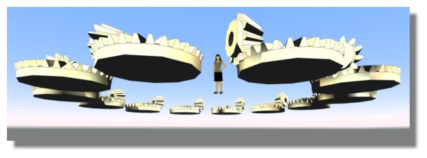
Images below and file attached.

Mike.


  Reply Reply More Options
Post Options
Reply as PM Reply as PM
Print Print
Mark as unread Mark as unread
Relationship Relationship
IP Logged

Previous
Next
 From:  Michael Gibson
6736.16 In reply to 6736.15 
Hi Mike, re:

> I think that it's a bit of a bodge because I couldn't find a way to extrude to the point that
> I wanted to extrude to which was vertically above the pitch circle I could only extrude to a
> point vertically above the centre of the bounding box - auto chosen (as far as I could tell)
> by the extrude-to-a-point function.

If the auto chosen tracking line is not what you need, you can make extrude to point freely pick the point by pushing the "Unlock direction" button in the command options:


- Michael

  Reply Reply More Options
Post Options
Reply as PM Reply as PM
Print Print
Mark as unread Mark as unread
Relationship Relationship
IP Logged

Previous
 From:  Mike (MGG942)
6736.17 In reply to 6736.16 
Aha!
Thank you, Michael, I hadn't noticed that.
Great.

Mike.
  Reply Reply More Options
Post Options
Reply as PM Reply as PM
Print Print
Mark as unread Mark as unread
Relationship Relationship
IP Logged
 

Reply to All Reply to All