Thanks Michael,
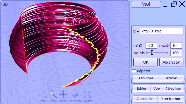
The script will do the job, an other usefull tool to use.
Still learning Moi, and still liking it, not that it goes along smoothly everytime but some headaches I could have with polymodeling are so simple here.
But I have to admit that sometimes its simplicity make things difficult, you have to make many action to get a simple result.
For example I had an hard time to cut a surface from a projected curve, I was not able to do it so I had to make a shape from the original curve and use it for a boolean diff.
But I will use this method more often as it seems to be the way to go. The downside is that it need a lot of planning and doesn't allow for a streamlined creation.
Many time I had to redo my shape because I made a mistake while constructing my shapes.
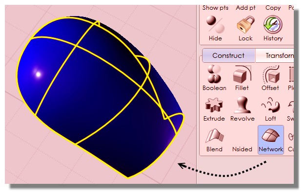
This for example, I build the flat shape from a curve but build only one half. I then made an offset shell to get my thickness but the result was not correct at the middle after doing a mirror.
There is a way to fix that or do I have to rebuild my curves? What I had in mid was to take the border edges and align them at the center and then merge the resulting shape. It's possible to do that?

Sometimes when I have finished my shape and I need to make a forgotten operation I'd like to retrieve the curves from my shape, is it possible?
I'd like to have just the exterior line to be converted as curves, but I didn't find a way to do so.
An other thing about this helmet is that I wanted to have each panel overlapping each others, like the real object. I suppose I have to do it with my curves or I can do it when my solid are built?
Here is the short lived result as I'm using the saveless version ;)
Not really happy with it but that's just an exercise and I learned a lot. That's a really simple object but it was a hard time.


One last question, is it possible to keep the object used to create a boolean and edit them while still seeing the change in the resulting boolean?
Something like meshfusion, you have a plane cutted by a cylinder and if you scale your cylinder you see the resulting boolean changing, same for any kind of boolean operation?