Learning the basics.
 1-20  21-40  41-48

Previous
Next
 From:  David marmor (DMARMOR)
6617.21 In reply to 6617.20 
Hi Michael
This time I have an issue while trying to build a shape using the sweep function.
I tried to follow this thread to build my shape but I can't get the same result.

Here is my curves, following the same color code from the thread, and the result I have.


The resulting file is attached too, do you know what I did wrong?
Thanks

  Reply Reply More Options
Post Options
Reply as PM Reply as PM
Print Print
Mark as unread Mark as unread
Relationship Relationship
IP Logged

Previous
Next
 From:  bemfarmer
6617.22 In reply to 6617.21 
Check out blue and black non-intersection?
  Reply Reply More Options
Post Options
Reply as PM Reply as PM
Print Print
Mark as unread Mark as unread
Relationship Relationship
IP Logged

Previous
Next
 From:  Frenchy Pilou (PILOU)
6617.23 
Why do you make Sweep ?
It's typical something for a Network!

  Reply Reply More Options
Post Options
Reply as PM Reply as PM
Print Print
Mark as unread Mark as unread
Relationship Relationship
IP Logged

Previous
Next
 From:  David marmor (DMARMOR)
6617.24 In reply to 6617.23 
I checked my intersection, I recreated the curves but there is always the same issue at the same spot. I was not able to track what is causing it.

I made a network but I had a pinching. I'll try to redo it.

Thanks for the support.


Edit: I tried to make the shape using network but it doesn't work. I get a funky shape, I have no clue what I am doing wrong.

EDITED: 14 Apr 2014 by DMARMOR

  Reply Reply More Options
Post Options
Reply as PM Reply as PM
Print Print
Mark as unread Mark as unread
Relationship Relationship
IP Logged

Previous
Next
 From:  bemfarmer
6617.25 In reply to 6617.24 
I moved the two end points of the right hoop to intersect, and network seemed to work very well.
  Reply Reply More Options
Post Options
Reply as PM Reply as PM
Print Print
Mark as unread Mark as unread
Relationship Relationship
IP Logged

Previous
Next
 From:  David marmor (DMARMOR)
6617.26 In reply to 6617.25 
I have to reload my last file as I did several change.
Here is how I cut my curves, maybe I am overdoing it.
But with these curves I cannot have a proper shape from network.


Ok I was able to make the network correctly but I have pinching at the end of the shape. That's why I wanted to use Pilou technique with the sweep.

Here is what I have at the end.

EDITED: 14 Apr 2014 by DMARMOR

Attachments:

Image Attachments:
Size: 30.3 KB, Downloaded: 4 times, Dimensions: 624x584px
  Reply Reply More Options
Post Options
Reply as PM Reply as PM
Print Print
Mark as unread Mark as unread
Relationship Relationship
IP Logged

Previous
Next
 From:  Michael Gibson
6617.27 In reply to 6617.21 
Hi David, re: sweep problem,

> The resulting file is attached too, do you know what I did wrong?

It looks like the same problem from this other recent thread here:
http://moi3d.com/forum/index.php?webtag=MOI&msg=6605.5

When you use a scaling rail the scaling rail must cover the entire extent above the rails - just making it touch the profile is not necessarily far enough if your profile is not planar and directly above the rails.

Sometimes it can be easier to construct things like this with more planar pieces like flat rails and then introduce warping later on using the Transform > Deform > Flow command (which is new for the upcoming v3 version), rather than using a lot of 3D warped rail curves from the start.

But anyway your particular sweep here can be fixed by extending the scaling rail in the side view so that it covers the entire area perpendicular above the rails like this:


And you're probably best off making the proflie for the sweep to be positioned perpendicular to the rails rather than having it start out in a slanted position, if you then want to introduce a slant at the end when you're done with the sweep use a boolean or trim to cut off the end with a line rather than trying to build a surface with slanted pieces right in the initial surface construction.

I've attached an example 3DM file here which should work better. Also I aligned the end point and first inside control points on the rails so that the curves are smooth where they touch rather than coming to a sharp angle where they connect.

- Michael

  Reply Reply More Options
Post Options
Reply as PM Reply as PM
Print Print
Mark as unread Mark as unread
Relationship Relationship
IP Logged

Previous
Next
 From:  Michael Gibson
6617.28 In reply to 6617.26 
Hi David,

> I have to reload my last file as I did several change.
> Here is how I cut my curves, maybe I am overdoing it.
> But with these curves I cannot have a proper shape from network.

Yeah it looks like you've cut them up into too many little pieces there. They need to form a grid layout, but the horizontal and vertical lines of the grid (sort of like lines of longitude and latitude on a globe) need to extend across the entire grid.

There's some more discussion on the type of arrangement that Network needs in some of these previous threads:
http://moi3d.com/forum/index.php?webtag=MOI&msg=4384.4
http://moi3d.com/forum/index.php?webtag=MOI&msg=1778.6


> Here is what I have at the end.

That kind of tip shaping tends to be a consequence of something that's not very uniform collapsing down to a single point.

To reduce it in Network it can be helpful to include a circle or arc curve near the tip so that things are more uniformly spaced just before they collapse down. See a couple of examples of that here:
http://moi3d.com/forum/index.php?webtag=MOI&msg=3623.14
http://moi3d.com/forum/index.php?webtag=MOI&msg=3550.6


It can be better in general to use more 2D construction though - revolve or rail revolve will tend to form the nicest perfectly round tips on closed objects, then in v3 there are new deformation tools that can be used to deform the smooth revolve onto a different path, see the attached example 3DM file, note here how every curve that went into making the end result was a planar curve that was flat to one of the top/front/right views, not any curves that are warped in 3D themselves. The final result has edge curves that warp in 3D but they're the result of construction from all 2D inputs...

- Michael
Attachments:

  Reply Reply More Options
Post Options
Reply as PM Reply as PM
Print Print
Mark as unread Mark as unread
Relationship Relationship
IP Logged

Previous
Next
 From:  David marmor (DMARMOR)
6617.29 In reply to 6617.28 
Thanks Michael,
I tested your file and the result with revolve rail is perfect.
One thing I'm not sure to understand is the last step. You did use flow with the blue curve to deform the resulting shape?
What is the purpose of the straight red curve?

But thanks for the tips, I will try to use it.

I'm still trying to build my shapes and that's funny how this method help me to understand better the shape, it will improve my polymodeling at the same time ;)

So here is a shape I'm trying to build.
I tried to apply the different techniques you shown me, but I have some difficutly with this case.
I build the main shape using sweep, and then I wanted to use 2D curves to cut it and produce my final result. But it didn't goes as I planned it.
When I followed my template to draw my curve on the side and cut the shape with it, the projected cut didn't follow my shape in the front view. So I tried to cut an other time in the front, but as you guessed it that didn't worked.
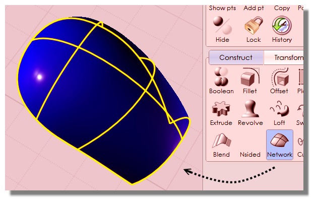
On the pictures I tried to make the curve in 3D and project it on the surface to trim it, but it doesn't resolve the issue.
As I understand it, it is because my volume doesn't intersect at the right place to conform my needs.

The yellow curve is what I want and the purple curve is the result.
How would you approach this?

Thanks

Edit: I found lyed helmet tutorial thread but the videos are not available, is there an other place to get them as it seems really usefull.


EDITED: 15 Apr 2014 by DMARMOR


  Reply Reply More Options
Post Options
Reply as PM Reply as PM
Print Print
Mark as unread Mark as unread
Relationship Relationship
IP Logged

Previous
Next
 From:  Michael Gibson
6617.30 In reply to 6617.29 
Hi David,

> One thing I'm not sure to understand is the last step. You did use flow with the blue
> curve to deform the resulting shape?
> What is the purpose of the straight red curve?

The Flow step used both the blue curve and also the red straight curve underneath it. That's how Flow works - it takes in a "base curve" and a "target curve", then remaps points from their relative position on the base curve onto the equivalent relative position on the target curve.

Usually the base curve will be a straight line running like a sort of backbone down the center of the thing you want to deform.


> The yellow curve is what I want and the purple curve is the result.
> How would you approach this?

It's tough for me to form a very good comment without being able to examine your actual geometry.

I'm confused as to why the projection does not match your drawn profile in the same 2D view, do you have the cutting curve placed at some kind of inclined angle or something? When you draw a 2D curve to cut with, the resulting cut in 3D should exactly match that same profile in the originating view.

- Michael
  Reply Reply More Options
Post Options
Reply as PM Reply as PM
Print Print
Mark as unread Mark as unread
Relationship Relationship
IP Logged

Previous
Next
 From:  David marmor (DMARMOR)
6617.31 In reply to 6617.30 
Hi Michael,

The file is at work so I can't give it to you now, sorry.
About the cut, the issue is not about the projected result from one view. The issue is when I project the drawn curve from the side view if I look through the front view the resulting cut is not matching in this view.
And if I draw the curve in the front view this will be the side view which won't match.
But I think it is completly normal as I'm projecting on a surface. That is my method that doesn't work but I don't have a clue on how to approch this.
I'm trying to make a sci fi helmet, nothing original here ;), but I don't know how to tackle this object.
It's not about tracing already accurate line work, it's about translating a 2D concept to 3D.
I made a sketch in Zbrush and then made a turntable from it, I then used the resulting image as template in MOI to try to reproduce a clean geometry.

Still a lot to learn to be proficient ;)
  Reply Reply More Options
Post Options
Reply as PM Reply as PM
Print Print
Mark as unread Mark as unread
Relationship Relationship
IP Logged

Previous
Next
 From:  Michael Gibson
6617.32 In reply to 6617.31 
Hi David,

> That is my method that doesn't work but I don't have a clue on how to approch this.

I guess the usual method is to pick just one of those views, either the front or the side as being the one of primary importance and using that.

If the projection does not result in what you want from another view, that really means that the surface is just not shaped in such a way to make that possible. If that's the case you would need to reconstruct the surface to be better suited for what you want to make.

If I could see the model or maybe know more information about the final end result you're trying to build I might be able to give better advice.

- Michael
  Reply Reply More Options
Post Options
Reply as PM Reply as PM
Print Print
Mark as unread Mark as unread
Relationship Relationship
IP Logged

Previous
Next
 From:  David marmor (DMARMOR)
6617.33 In reply to 6617.32 
Hi Michael,

Here is basically the shape I want to build, I made it quickly to illustrate the main problem I have. The bulge on the back and on the side are just here to say that it is not a primary shape and you can't take a sphere and deform it, maybe you can/should?

So my problem is about the cut in front. When I follow the side and trim on my main shape, the front will not follow.
I'm pretty sure that is because of my main shape, and that's the core of my issue, how do you build your main shape to be sure it will fit all your cut in any views. And do you have to tackle this problem like this.
An other thing would be to trace the outline of the shape and build my surface but with that many curve it will produce bulge and imprecise surface.

Sorry for all the newbish question, I still have a lot of homework to do :)


Attachments:

  Reply Reply More Options
Post Options
Reply as PM Reply as PM
Print Print
Mark as unread Mark as unread
Relationship Relationship
IP Logged

Previous
Next
 From:  Michael Gibson
6617.34 In reply to 6617.33 
Hi David,

> I'm pretty sure that is because of my main shape, and that's the core of my issue, how
> do you build your main shape to be sure it will fit all your cut in any views.

So I guess that normally you would just not go about it in this particular way of trying to control a cut profile from 2 different directions at the same time...

Focus on one cut direction and on how to form the main shape.


> The bulge on the back and on the side are just here to say that it is not a primary shape
> and you can't take a sphere and deform it, maybe you can/should?

It's maybe possible to deform a sphere but it's hard to get very localized features that way. It looks to me like you've still got a primary shape under that outline, notice how there is basically a pattern that starts at the base and continues above the bumps, here I've traced it with red:


Try to ignore the localized bumps and just work on the non-bumped underlying full form. Try to build a base shape that matches that outline first before starting to get into cuts.

- Michael
Attachments:

  Reply Reply More Options
Post Options
Reply as PM Reply as PM
Print Print
Mark as unread Mark as unread
Relationship Relationship
IP Logged

Previous
Next
 From:  David marmor (DMARMOR)
6617.35 
Hi Michael,
A quick post to show you what I meant by the cut not having the expected result on each view.


Here I draw my curve from the front and trim on my shape. The cut is as expected on the front but it doesn't match on the side.


Now I made the cut on the side, and the result doesn't match the front =)


I guess it is normal and I have to draw the cut in both view.
But If I move the curve to meet both view we can see that it can't match the shape I built.
So I'm clueless :)


  Reply Reply More Options
Post Options
Reply as PM Reply as PM
Print Print
Mark as unread Mark as unread
Relationship Relationship
IP Logged

Previous
Next
 From:  TpwUK
6617.36 In reply to 6617.35 
Hi David, you have run into a common problem associated with drawing from prints. 2D flat drawings can''t represent curvature and perspective/parallax. It's a nightmare where the outlines look great until you try to use them and then you find out things don't line up correctly from the different views, so in circumstances like this 'artistic licence' comes into play. You will not succeed in trying to copy this perfectly, you will have to model this on the principle of what it looks like. As long as it is 'close enough' then it should be fine.

The other alternative is to get a picture of a persons head that offers a front and side view. The use something like photoshop or gimp or whatever photo editor software you use. Import your helmet outline for each view then use stretch and scale to make the helmet fit the persons head better, then save them out and then try modelling from them again.

The above theory is great as long as it's a helmet ment for a human head. If it's an alien helmet then you are free to model it according to fantasy rules.

Martin Spencer-Ford
  Reply Reply More Options
Post Options
Reply as PM Reply as PM
Print Print
Mark as unread Mark as unread
Relationship Relationship
IP Logged

Previous
Next
 From:  David marmor (DMARMOR)
6617.37 In reply to 6617.36 
Hi Martin,
Thanks for the explanation, and in fact the way I made my kind of helmet was to test this.

If I had to sculpt this shape I won't have any problem as I'll be able to resolve it while I'm sculpting.
My issue here is how to translate this same process to MOI.
If I trace the cut in 3D space and build my shape from many curves in 3D I'll loose the advantage of using nurbs and I think I will have a blobby result and have a hard time to make it smooth, the very same issue you can have in polymodeling if you have too much edges.

What I have in mind at the moment is how to find a way to buid my shape while still having it to support the cuts.
I have to test this out ;) I wish Lyed helmet tutorial was still available, too bad to see these kind of ressources disappearing because of bad hosting.
  Reply Reply More Options
Post Options
Reply as PM Reply as PM
Print Print
Mark as unread Mark as unread
Relationship Relationship
IP Logged

Previous
Next
 From:  Michael Gibson
6617.38 In reply to 6617.37 
Hi David, I'm not really sure what to tell you - it's difficult to control things in the way you're trying to do here with basically trying to reverse engineer how the shape has to be in order to generate the cut you want from the other direction.

Usually with NURBS things are not done in this way, usually there is more of a focus on profiles generating the main shape instead of focusing on the cuts to try and generate the main shape from.

I guess when you don't get the right form from the other direction of your cuts, the deviation there is giving you some information about how you need to manipulate the main shape in order to bring it closer to what you want. So then you probably have to edit the curve at the bottom to make a more tapered shape or something that will come closer to what you want.

I think for your case here it's something like your shape needs to be a lot less sphere like, the widest point needs to be more near the back and it has to taper in a ways at least that's what it seems like...

But it's not very easy to define a shape in this particular way that you're trying to do here...


If you don't really know what shape you want but instead want to derive that shape by incrementally pushing things around, that whole method of point tweaking is more suited for a sub-d or displacement brush sculpting program rather than a NURBS program. The NURBS toolset is more oriented around the concept of you knowing a bit more directly what the base shape should be formed like.

- Michael
  Reply Reply More Options
Post Options
Reply as PM Reply as PM
Print Print
Mark as unread Mark as unread
Relationship Relationship
IP Logged

Previous
Next
 From:  Michael Gibson
6617.39 In reply to 6617.37 
Hi David, so I think in order to get the kind of cut profiles that you want you'd need a shape more like this (also see attached 3DM file):


But this is just not really the way that you'd want to work with things in MoI - you'd want to know before hand that you wanted a shape with a kind of tapering and indentation in it from the beginning rather than trying to start out with a fairly different shape and then try to mutate it to match your end profiles. That's a very sub-d modeling type of process, it's just not what NURBS modeling is really suited for.

I mean it's not like you can't experiment with shapes in MoI, but in a case like you have here it's really a type of organic shape modeling that you're trying to do, with the end result being not a very uniform regularized shape. The more that you get into this type of territory where the thing you want is some kind of result of squashing small zones of the shape around in 3D, the more you leave the territory where NURBS modeling is good at and you go more into the territory where sub-d modeling is good at.

The main difference in these cases is that the profiles you're trying to use do not really fully define the model shape, they're more of a product of some organic shape. It's similar when doing a human face for example - sure a human face has a profile that can be captured at any one particular angle, but that profile alone does not fully define the shape like it does with an extrusion or revolve since the shape changes a whole lot right as you leave that immediate area that the profile happened to capture.

The more the thing you're trying to model fits into that kind of category of "not fundamentally defined by 2D profile curves", the less of a fit that particular thing is for NURBS modeling and the better it fits with sub-d modeling.

- Michael

  Reply Reply More Options
Post Options
Reply as PM Reply as PM
Print Print
Mark as unread Mark as unread
Relationship Relationship
IP Logged

Previous
Next
 From:  David marmor (DMARMOR)
6617.40 In reply to 6617.39 
Thank you Michael for your patience.
I wrote an answer at work but I certainly made a mistake as I didn't post it.
In substance I was saying that I made the worst shape ever, I did it quickly to illustrate my point but I didn't take into account the final result, just thinking these two views would be enough.
The resulting shape is something close to what you have done and won't produce anything elegant, at least not something I had in mind.
But I will continue to test MOI as I have faith in it =)
I'm sure it can produce fast iteration, at least that's what I want to do. But I have a lot to learn and I have to admit that it is still pleasent to work with it, and it made me improve my subd skills.

I'll do more exercices to see which issue I encounter and how to resolves them.
Thanks for your support.
  Reply Reply More Options
Post Options
Reply as PM Reply as PM
Print Print
Mark as unread Mark as unread
Relationship Relationship
IP Logged
 

Reply to All Reply to All


Show messages:  1-20  21-40  41-48