Scherk's second minimal surface script
 1-20  21-34

Next
 From:  bemfarmer
6524.1 
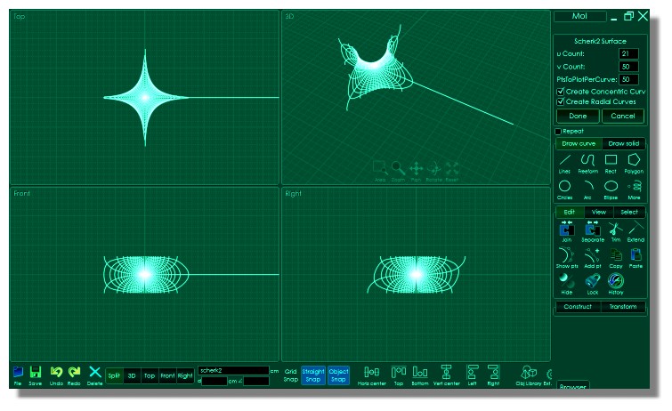
Here is a script to create most of Scherk's second minimal surface.
Note that the Wikipedia equations, as well as the Wolfram equations, are faulty. The y parametric equation should have ln in front of it,
similar to the x equation. The correct equations are shown here: http://www.math.mcgill.ca/gantumur/math580f12/minimal_surfaces.pdf

The literature states that the parametric equations are difficult to plot. An angle of 0, as well as a radius of 1 would cause division by zero, which
javascript, and MoI do not like. So an initial 2PI angle was substituted for 0.
The last "concentric" curve was discarded, due to its irregularity, and semicircles substituted to enable network. Afterwards, they were trimmed
off with red planes. So the surface should be the minimal surface, within a very small tolerance.
The curves in red were added manually.
The basic surface can be stacked, by rotation about the upper or lower red rotation line.
With such a stack, Flow and Twist could be done.

So this script is probably one that would only be used once. The surface is now created, so the script is not needed :-)

- Brian


EDITED: 19 Apr 2016 by BEMFARMER

Attachments:

  Reply Reply More Options
Post Options
Reply as PM Reply as PM
Print Print
Mark as unread Mark as unread
Relationship Relationship
IP Logged

Previous
Next
 From:  Frenchy Pilou (PILOU)
6524.2 
Normal bug ?

---
Pilou
Is beautiful that please without concept!
My Gallery
  Reply Reply More Options
Post Options
Reply as PM Reply as PM
Print Print
Mark as unread Mark as unread
Relationship Relationship
IP Logged

Previous
Next
 From:  bemfarmer
6524.3 In reply to 6524.2 
Hi Pilou,
Making the number of points, less 1, in the script, divisible by 4, results in 4 long lines at angles PI/2, PI, 3PI/2, and 2PI.
Then the "radial" curves seem to be more symmetric.
There are 4 quadrants, so being congruent to 0 modulus 4 seems helpful.
The original script uses 21, 161, and 101, which give quite a lot of curves, and after fixing up the outer perimeter, are network-able.
I think this is because the values near these angles change a great deal with small perturbations.
The equations are not nice and uniform.

- Brian

EDITED: 19 Feb 2014 by BEMFARMER

  Reply Reply More Options
Post Options
Reply as PM Reply as PM
Print Print
Mark as unread Mark as unread
Relationship Relationship
IP Logged

Previous
Next
 From:  bemfarmer
6524.4 
This script creates Scherk's First Minimal Surface. The surface looks like a saddle, and may even be useful.
The u and v angle parameters have intervals of (-PI/2, PI/2), inclusive.
Larger intervals do not work. This is probably due to division by zero?

A small absolute value for cValue makes the "saddle" flatter. When cValue is .00001, the grid is almost flat.
A negative cValue faces the horse in the direction of the x axis.
The maximum absolute value for cValue is coded to 1.0. cValue of zero is coded to 1.0.
Network works for cValue = .99.
A faster .htm version could be done.

- Brian


EDITED: 2 Apr 2015 by BEMFARMER


  Reply Reply More Options
Post Options
Reply as PM Reply as PM
Print Print
Mark as unread Mark as unread
Relationship Relationship
IP Logged

Previous
Next
 From:  TOM (SIRTOM)
6524.5 In reply to 6524.4 
https://people.eecs.berkeley.edu/~sequin/SCULPTS/scherk.html


This tool is fantastic for easy transformations of any kinds on the basic minimal surface
- but I need to build some variations as based on Nurbs.

i hoped to reconstruct it in MOi by importimg an expoerted obf.file, bit no way.

So I hope to find somw helpful tips how to proceed in MOI
  Reply Reply More Options
Post Options
Reply as PM Reply as PM
Print Print
Mark as unread Mark as unread
Relationship Relationship
IP Logged

Previous
Next
 From:  Michael Gibson
6524.6 In reply to 6524.5 
Hi Tom, if the generator makes triangulated polygon data then that tends to be a difficult task to convert to NURBS.

One possibility would be to use retopology tools in 3D Coat or something like Topogun to get a quad polygon layout and then use Max's sub-d to NURBS script to convert that to NURBS.

The other possibility is to look at reverse engineering methods which are for converting triangle mesh scanned data into NURBS, often times these work similar to retopology methods where you trace out quad boundaries on the mesh and it fits NURBS surfaces to it. They tend to be rather expensive specialized tools though, see here for some links:

http://moi3d.com/forum/index.php?webtag=MOI&msg=8460.2

- Michael
  Reply Reply More Options
Post Options
Reply as PM Reply as PM
Print Print
Mark as unread Mark as unread
Relationship Relationship
IP Logged

Message 6524.7 deleted 13 Jul 2017 by BEMFARMER

Previous
Next
 From:  TOM (SIRTOM)
6524.8 In reply to 6524.6 
Thank you Michael. unfortunately I don´t own those tools.

Building up the curves is relatively easy, but generating perfectly
smooth surfaces is definitely not. see attachment. (Surface deleted already)

PS uploading attachment does not work
500 - Internal server error.
There is a problem with the resource you are looking for, and it cannot be displayed.
Attachment without the obj worked

EDITED: 14 Jul 2017 by SIRTOM

Attachments:

  Reply Reply More Options
Post Options
Reply as PM Reply as PM
Print Print
Mark as unread Mark as unread
Relationship Relationship
IP Logged

Previous
Next
 From:  TOM (SIRTOM)
6524.9 In reply to 6524.8 
@ bemfarmer

Is there a way to manipulate the parameters of your script so the saddle will match the blue curves of
the imported Scherk-Collins surface ?

EDITED: 15 Jul 2017 by SIRTOM

Attachments:

Image Attachments:
Size: 40.8 KB, Downloaded: 61 times, Dimensions: 700x760px
  Reply Reply More Options
Post Options
Reply as PM Reply as PM
Print Print
Mark as unread Mark as unread
Relationship Relationship
IP Logged

Previous
Next
 From:  Mike (MGG942)
6524.10 In reply to 6524.5 
Tom,

I recently 3D printed a model of this.
I got an .obj file from MathMod and then made it solid in MeshMixer.

I've just checked and can confirm that the MathMod .obj file can be imported into Moi using the importobj script.

Mike.
  Reply Reply More Options
Post Options
Reply as PM Reply as PM
Print Print
Mark as unread Mark as unread
Relationship Relationship
IP Logged

Previous
Next
 From:  bemfarmer
6524.11 In reply to 6524.9 
Hi Tom,
Off the cuff, perhaps setting up a Frame, which "moves the x,y,z axi?"

What are the coordinates and orientation of your required position?

- Brian

Or use Orient command?

EDITED: 15 Jul 2017 by BEMFARMER

  Reply Reply More Options
Post Options
Reply as PM Reply as PM
Print Print
Mark as unread Mark as unread
Relationship Relationship
IP Logged

Previous
Next
 From:  bemfarmer
6524.12 In reply to 6524.11 
I ran the old sherk2 script again, and applied some different MoI commands.

Lineweb will form a curve between the endpoints of a bunch of curves originating from a single point, with point count = 2.

Rather than arc, Blend was used to connect the ends, then Join. The long lines were trimmed.

Network then works quickly.

Each blend arc and face was then deleted with a plane.

Move and rotate then extended the Sherk2 surface.

- Brian
Image Attachments:
Size: 5.8 KB, Downloaded: 46 times, Dimensions: 160x120px
  Reply Reply More Options
Post Options
Reply as PM Reply as PM
Print Print
Mark as unread Mark as unread
Relationship Relationship
IP Logged

Previous
Next
 From:  TOM (SIRTOM)
6524.13 In reply to 6524.10 
>>I've just checked and can confirm that the MathMod .obj file can be imported into Moi using the importobj script<<

You are right and no problems there. Where I had problems was uploading the obj onto the MOI discussion forum
  Reply Reply More Options
Post Options
Reply as PM Reply as PM
Print Print
Mark as unread Mark as unread
Relationship Relationship
IP Logged

Previous
Next
 From:  TOM (SIRTOM)
6524.14 In reply to 6524.12 
Very good and thank you, Brian.

Hope I can follow your steps and will give it a try !
  Reply Reply More Options
Post Options
Reply as PM Reply as PM
Print Print
Mark as unread Mark as unread
Relationship Relationship
IP Logged

Previous
Next
 From:  TOM (SIRTOM)
6524.15 
Brian I realized I cabt follow the steps you layed out.

First, why have you used Scherk2 and not Scherk1 ?
  Reply Reply More Options
Post Options
Reply as PM Reply as PM
Print Print
Mark as unread Mark as unread
Relationship Relationship
IP Logged

Previous
Next
 From:  bemfarmer
6524.16 In reply to 6524.15 
The Scherk tower is made with Scherk 2nd surface.

Your model resembles a Scherk tower, but reference is made to the Scherk-Collins surface (which is non-minimal)

so after rereading your post, I see that the "saddle surface ring" Scherk-Collins surface:
"can be formed by twisting and warping a singly-periodic Scherk’s minimal surface"
so I'm doing some more reading, both art and math... :-)

https://pdfs.semanticscholar.org/8ac1/d46735688959ec7f1f58a92dd268d0e1388c.pdf

The Scherk1

- Brian

I did try out the mathmod and sculpture generator programs a bit.

I'm going to try stacking some Scherk1 saddles using c=0.99, u = 25, v = 25, 100 pts/curve, trimming the tops and bottoms,
copying above and below, rotate 90 degrees, blending, then network...

EDITED: 17 Jul 2017 by BEMFARMER

  Reply Reply More Options
Post Options
Reply as PM Reply as PM
Print Print
Mark as unread Mark as unread
Relationship Relationship
IP Logged

Previous
Next
 From:  TOM (SIRTOM)
6524.17 In reply to 6524.16 
Hi Brian,

Thank you for your input.

Ok thats clear now, I wasnt sure which of your scripts to use.

The original obj was created with this prog
https://people.eecs.berkeley.edu/~sequin/SCULPTS/scherk.html
Great functionality to interactively twist and bend all kind of Scherk towers

I transformed the file generated there into an obj, imported it into MOI
and built uo the curves manually expecting to find a way to create surfaces
out of them,
  Reply Reply More Options
Post Options
Reply as PM Reply as PM
Print Print
Mark as unread Mark as unread
Relationship Relationship
IP Logged

Previous
Next
 From:  bemfarmer
6524.18 In reply to 6524.17 
There is source code for SculptGen. I've no idea if it can be modified to make nurbs, or which MoI commands could do
equivalent twisting and bending...

After work I'll try to blend together the Scherk1 script output.

- Brian
  Reply Reply More Options
Post Options
Reply as PM Reply as PM
Print Print
Mark as unread Mark as unread
Relationship Relationship
IP Logged

Previous
Next
 From:  bemfarmer
6524.19 
The Scherk1 surface can be copied/moved, by PI units in the x direction and also PI units in the y direction, checkerboard fashion.
PI (+/-), is the length of an unwrapped circle of diameter 1 unit.

I read that the Bonnet transformation, with theta = 90 degrees, turns a Scherk1 into a Scherk2 surface. (?How to script?:-)
(Also applies for catenoid/helicoid, and for D, gyroid, P surfaces...)

- Brian
  Reply Reply More Options
Post Options
Reply as PM Reply as PM
Print Print
Mark as unread Mark as unread
Relationship Relationship
IP Logged

Previous
Next
 From:  TOM (SIRTOM)
6524.20 In reply to 6524.18 
>>I've no idea if it can be modified to make nurbs<<
Very interested in hearing more about
  Reply Reply More Options
Post Options
Reply as PM Reply as PM
Print Print
Mark as unread Mark as unread
Relationship Relationship
IP Logged
 

Reply to All Reply to All


Show messages:  1-20  21-34