How to set curve point that will determine the extrusion line

Next
 From:  Metin Seven (SEVENSHEAVEN)
6327.1 
Hi guys,

I'd love to know how I can determine what closed curve point will be the visible line when the curve is extruded. I assume that the visible line on the side of an extruded curve is the edge where the side surface of the extrusion starts and ends?

Thanks!

Metin
  Reply Reply More Options
Post Options
Reply as PM Reply as PM
Print Print
Mark as unread Mark as unread
Relationship Relationship
IP Logged

Previous
Next
 From:  Frenchy Pilou (PILOU)
6327.2 In reply to 6327.1 
Any curve can be used as "profil" for an Extrude

And any curve can be used as Path for the extrusion! ;)

Of course result depend of a good choice of these 2 curves! :)
  Reply Reply More Options
Post Options
Reply as PM Reply as PM
Print Print
Mark as unread Mark as unread
Relationship Relationship
IP Logged

Previous
Next
 From:  Metin Seven (SEVENSHEAVEN)
6327.3 
Merci Pilou. :) But how can I determine which point on a closed curve translates to the visible edge line on the side of an extrusion?
  Reply Reply More Options
Post Options
Reply as PM Reply as PM
Print Print
Mark as unread Mark as unread
Relationship Relationship
IP Logged

Previous
Next
 From:  Frenchy Pilou (PILOU)
6327.4 In reply to 6327.3 
When you click on a curve and move it: it's a point of this curve, and when you move it you have some labels on snaped surface for help you!

But post a little file 3dm of your problem!


ps I don't know what do you want make with your curves on the surface but maybe this can help you!
It's not points of curve on the surface but adding control points of the surface!
You can of course call the Add Points function several times!

Surface must be selected before calling the Function!


Now you can move any control points and the surface will follow them! ;)

A cool sort of organic modeling with nurbs! :)

EDITED: 3 Dec 2013 by PILOU

  Reply Reply More Options
Post Options
Reply as PM Reply as PM
Print Print
Mark as unread Mark as unread
Relationship Relationship
IP Logged

Previous
Next
 From:  Metin Seven (SEVENSHEAVEN)
6327.5 
Merci encore, Pilou. :)

Here's an illustration of my question:


Do I have to trim the curve before extruding, or is there an easier way to determine the point that will become the extrusion line?

EDITED: 3 Dec 2013 by SEVENSHEAVEN


  Reply Reply More Options
Post Options
Reply as PM Reply as PM
Print Print
Mark as unread Mark as unread
Relationship Relationship
IP Logged

Previous
Next
 From:  coi (MARCO)
6327.6 In reply to 6327.5 
there was a thread about something quite similar..might be some answers in there

http://moi3d.com/forum/index.php?webtag=MOI&msg=5801.1
  Reply Reply More Options
Post Options
Reply as PM Reply as PM
Print Print
Mark as unread Mark as unread
Relationship Relationship
IP Logged

Previous
Next
 From:  milkywaif
6327.7 In reply to 6327.5 
Hi Metin. Any closed curve primitive you create in top/front/right viewport will have start/end point located at rightmost. You should create your curve considering this.
- Evren
  Reply Reply More Options
Post Options
Reply as PM Reply as PM
Print Print
Mark as unread Mark as unread
Relationship Relationship
IP Logged

Previous
Next
 From:  Frenchy Pilou (PILOU)
6327.8 
Ah ok ! So this post will be your friend! :)
http://moi3d.com/forum/index.php?webtag=MOI&msg=5288.21

before the Enter of the Loft for Apply it you can move any points of the Start End Curves!

The command MarkCurveStart is on the previous post!


PS Carreful at the end of the last Copy Move extract

you must click the surface then click the curve of this surface and not the curves generator!

EDITED: 3 Dec 2013 by PILOU

  Reply Reply More Options
Post Options
Reply as PM Reply as PM
Print Print
Mark as unread Mark as unread
Relationship Relationship
IP Logged

Previous
Next
 From:  Metin Seven (SEVENSHEAVEN)
6327.9 
Thanks a lot guys, learning MoI step by step. :)

———————

sevensheaven.nl — 3D (print) modeling • animation • characters • icons • illustration • infographics • logos • visualization

  Reply Reply More Options
Post Options
Reply as PM Reply as PM
Print Print
Mark as unread Mark as unread
Relationship Relationship
IP Logged

Previous
Next
 From:  Michael Gibson
6327.10 In reply to 6327.7 
Hi Evren,

> Hi Metin. Any closed curve primitive you create in top/front/right viewport will have start/end
> point located at rightmost. You should create your curve considering this.

It won't always be the rightmost, it will be where you happened to place the first point of the curve. You must tend to draw them with your first point placed towards the right.

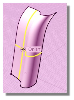
Every closed curve still has a start and end point on it, even when the curve is a "periodic" smooth closed curve which has its control point set up so that it does not form a sharp corner point at the closing area. With a smooth curve, the start and end touch each other and that's called the "seam" point of the curve.

When you extrude a curve into a surface, the seam point of the closed curve will become the seam edge of the closed surface generated from it.

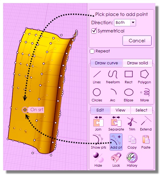
The seam point of a closed periodic curve is not really visible, you can mark it with a point using this plug-in here though:
http://moi3d.com/forum/index.php?webtag=MOI&msg=5288.21

The seam edge of a closed periodic surface is more visible since it is present in the edge topology structure of the object.


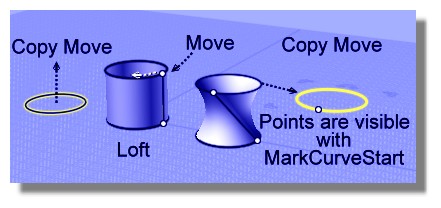
@Metin: - hopefully this makes some more sense now. There is not currently any easy way set up to edit the seam point of a closed periodic curve. Why is it that you're trying to change that in the first place? It is possible to do some manipulation of the seam if you use Loft instead, I think that's shown above...

In the future I do want to add in a tool to edit the seam point of a curve, right now I do not have the UI set up to house those kinds of detailed low level editing tools quite yet though.

- Michael
  Reply Reply More Options
Post Options
Reply as PM Reply as PM
Print Print
Mark as unread Mark as unread
Relationship Relationship
IP Logged

Previous
Next
 From:  milkywaif
6327.11 In reply to 6327.10 
>> It won't always be the rightmost, it will be where you happened to place the first point of the curve. You must tend to draw them with your first point placed towards the right.

I meant, for primitives like circle, ellipse, etc with "center" option where you can't actually place any points of the curve you're creating. In that case, MoI always places first/last points at rightmost for top, front, right views (opposite for bottom, back, left views)

EDITED: 3 Dec 2013 by MILKYWAIF

  Reply Reply More Options
Post Options
Reply as PM Reply as PM
Print Print
Mark as unread Mark as unread
Relationship Relationship
IP Logged

Previous
Next
 From:  Michael Gibson
6327.12 In reply to 6327.11 
Hi Evren, yeah for something like a circle by center point, the "seam point" of the circle will be located on the positive x-axis direction of the construction plane that it was drawn on.

For the particular case of a circle you can move its seam point around just by rotating it.

The type of closed curve I was talking about before was one where you draw a squishy curve using Draw curve > Freeform > Control points.

- Michael
  Reply Reply More Options
Post Options
Reply as PM Reply as PM
Print Print
Mark as unread Mark as unread
Relationship Relationship
IP Logged

Previous
Next
 From:  DannyT (DANTAS)
6327.13 In reply to 6327.12 
Hi Michael,

Is the seam in all NURB surfaces? not only in MoI I'm talking in general, it's only when discovering MoI I've come across the seam all other CAD packages don't show a seam I'm assuming it's there, only not shown, is this correct?

-
~Danny~
  Reply Reply More Options
Post Options
Reply as PM Reply as PM
Print Print
Mark as unread Mark as unread
Relationship Relationship
IP Logged

Previous
Next
 From:  Michael Gibson
6327.14 In reply to 6327.13 
Hi Danny, all NURBS surfaces have an implicit starting and ending location, but some CAD systems like ones based on Parasolid do allow trimming boundaries to cross over that parametric seam as if it weren't there and so the seam might not be represented in their 3D edge topology.

That makes for a fairly more complex type of internal trimming structure than one where each edge maps to one single curve in the UV parameter space though.

But that sort of does move the seam to something that's treated more by internal program logic rather than directly represented in the visible topology.

- Michael

EDITED: 3 Dec 2013 by MICHAEL GIBSON

  Reply Reply More Options
Post Options
Reply as PM Reply as PM
Print Print
Mark as unread Mark as unread
Relationship Relationship
IP Logged

Previous
Next
 From:  DannyT (DANTAS)
6327.15 In reply to 6327.14 
Thanks for the clarification Michael.

The reason I ask is I notice a lot of users get hung up on the seam, it's okay for the users who understand that it doesn't affect the final outcome of the surface I was wondering is it possible to make it invisible in MoI however it seems :) that the seam in MoI has more affect on features i.e. Blends than other CAD packages so maybe I've answered my own question and we need to know where the seam is in MoI so we can manipulate it to get secondary features to work when it's apparent that the seam is affecting the calculation.

-
~Danny~
  Reply Reply More Options
Post Options
Reply as PM Reply as PM
Print Print
Mark as unread Mark as unread
Relationship Relationship
IP Logged

Previous
Next
 From:  Michael Gibson
6327.16 In reply to 6327.15 
Hi Danny,

> I was wondering is it possible to make it invisible in MoI

I suppose that could be possible... It would still be there in the actual geometry though and when it comes into play it might kind of make things even more mysterious at that point.

Like if you take a cylinder and boolean a hole that goes through the seam, the edges for the hole will be split up where they ran into the seam. Even if the seam is just cosmetically hidden, that kind of behavior will still happen.

So it's kind of hard to weigh whether hiding the seam would lead to less confusion overall or not in the long run... Maybe in the future I can experiment with it.

- Michael
  Reply Reply More Options
Post Options
Reply as PM Reply as PM
Print Print
Mark as unread Mark as unread
Relationship Relationship
IP Logged

Previous
Next
 From:  Metin Seven (SEVENSHEAVEN)
6327.17 
Hi Michael et al,

Thanks for the elucidations, much appreciated.

The reason for my question was that I figured that having a seam's orientation aligned to the seams of other parts of a 3D model will cause better topology continuity after boolean operations. For example, when I trim a cap of an extruded or lofted curve, I tend to trim it from the seam to the opposite side, and blend the two halves. But if the seam doesn't matter much, then I'll forget this. I did notice that having seams exactly aligned can cause fillets to fail after a boolean union.
  Reply Reply More Options
Post Options
Reply as PM Reply as PM
Print Print
Mark as unread Mark as unread
Relationship Relationship
IP Logged

Previous
Next
 From:  Michael Gibson
6327.18 In reply to 6327.17 
Hi Metin, it is true that sometimes the placement of the seam can be significant, especially if it's placed in such a way that causes some short edge fragment to be created, that can then cause problems later on for filleting because fillets won't work if they have to totally consume away an entire current edge.


> I did notice that having seams exactly aligned can cause fillets to fail after a boolean union.

The worse kind of thing is if the seams are _almost_ aligned to one another but not quite, making a little tiny edge fragment between them.


So yes there are some situations where due to limits and problems in some operations (particularly filleting) where it can be good to pay attention to the seam location, but you don't necessarily have to worry about it with every single extrude either... With the particular example that you posted originally it's not clear to me why you would need to worry about it there.

- Michael
  Reply Reply More Options
Post Options
Reply as PM Reply as PM
Print Print
Mark as unread Mark as unread
Relationship Relationship
IP Logged

Previous
 From:  Metin Seven (SEVENSHEAVEN)
6327.19 In reply to 6327.18 
Thanks Michael,

My example was an isolated shape I would turn into a nose solid, to be boolean-unioned with a sphere that would become the head.

———————

sevensheaven.nl — 3D (print) modeling • animation • characters • icons • illustration • infographics • logos • visualization

  Reply Reply More Options
Post Options
Reply as PM Reply as PM
Print Print
Mark as unread Mark as unread
Relationship Relationship
IP Logged
 

Reply to All Reply to All