Hidden line removal progress
 1-3  …  244-263  264-283  284-296

Previous
Next
 From:  Mike K4ICY (MAJIKMIKE)
6201.284 In reply to 6201.283 
Thanks Ed,

Corel made some improvements to the tracing feature after X4, as X3's tracing was just horrible. I'm using X6.
As tracing line-art is a staple of my daily work I religiously use Corel 12's stand-alone TRACE program. It lends itself to hand-drawn art and will take bitmaps of virtually any size.
But for some stinking reason they dropped it at X3. I keep a version 12 CD in store, but I worry that I'll lose it someday.
I prefer AI's trace next to that one, which is a vestigial of Streamline, but since I use Corel as my primary and AI as secondary, I rarely touch AI's tracer.
X6's is not that great on drawing but actually does well with basic logos and simple fonts inside of logos.

There are very few setting offered, but they do allow you now to get stacked objects like the old TRACE as an alternative to the odd cut-out ones.

I've been wishing for an output feature like this for a while, but since this came under my radar, I'm just now grasping the possibilities.

I would like there to be some way to get a filled vector shape instead of the bitmap, but I know that for one, the bitmap is rendered from surface polys - and two; the outer outline silhouettes consist of many broken and oddly overlapped segments. A white bitmap would work fine, but all said, this request can be satisfied with a bit of quick levels and trace work in Corel. I ain't complainin' ;-)
  Reply Reply More Options
Post Options
Reply as PM Reply as PM
Print Print
Mark as unread Mark as unread
Relationship Relationship
IP Logged

Previous
Next
 From:  Michael Gibson
6201.285 In reply to 6201.281 
Hi Mike, woah that is awesome, your pic confused me for a second about why you were showing that photo! :)


> Could there be a way to use a blank white or solid-color vector object in place of the bitmap?

This is fairly difficult because getting a vector object fill means actually joining together numerous different generated pieces and trying to screen out little fragments of things. I don't really have much hope of getting that done anytime too soon.


> Or could there be a way to tell the 'background' bitmap to be white without disappearing
> and showing the outlines beneath?

This one is possible currently by adjusting some lighting settings, just add another one to your lighting presets. The parameters you would set are shown here:
http://moi3d.com/forum/index.php?webtag=MOI&msg=3135.3

Basically if the light intensity is turned up very high it will have full brightness everywhere essentially disabling shading.

- Michael
  Reply Reply More Options
Post Options
Reply as PM Reply as PM
Print Print
Mark as unread Mark as unread
Relationship Relationship
IP Logged

Previous
Next
 From:  blowlamp
6201.286 In reply to 6201.281 
Mike.

That is SO convincing, it's just NOT TRUE!!!!

Looks like you've been carrying it around in your wallet for the last forty years.

Absolutely brilliant :-()


Martin.
  Reply Reply More Options
Post Options
Reply as PM Reply as PM
Print Print
Mark as unread Mark as unread
Relationship Relationship
IP Logged

Previous
Next
 From:  danperk (SBEECH)
6201.287 
A little icon work & transparency.
Image Attachments:
Size: 262 KB, Downloaded: 73 times, Dimensions: 1167x792px
  Reply Reply More Options
Post Options
Reply as PM Reply as PM
Print Print
Mark as unread Mark as unread
Relationship Relationship
IP Logged

Previous
Next
 From:  wastzzz
6201.288 
I noticed few difference in accuracy between MoI's hidden line removal and Rhino's Make2D command.
I am attaching an example of the same 3D model.
MoI output is not bad, but Rhino's one is more accurate (lines are touching and it allows me to use hatching later).
Canvas size was 70. Anyways I'm pretty fine with the MoI output, but could you explain me how the hidden line removal algorithms of MoI and Rhino are different? Are they using a different approach?
Is it possible in the future to improve the hidden line feature to get better results at corners/touching lines?
It's just my own curiosity.

MoI:


Rhino:


Thank you.
M.
Attachments:

  Reply Reply More Options
Post Options
Reply as PM Reply as PM
Print Print
Mark as unread Mark as unread
Relationship Relationship
IP Logged

Previous
Next
 From:  Bard (BFM)
6201.289 In reply to 6201.46 
Hello Mike K4ICY, beau bee, bee, buzz, balèze (hulk, huge) in the MoI galery.
  Reply Reply More Options
Post Options
Reply as PM Reply as PM
Print Print
Mark as unread Mark as unread
Relationship Relationship
IP Logged

Previous
Next
 From:  Michael Gibson
6201.290 In reply to 6201.288 
Hi Max, I think that Rhino's one is based on intersecting curves with one another, while MoI's one is based on following a curve and using a pixel depth buffer to determine whether things are hidden or not.

So yeah they use a different approach and that's part of why they have different abilities too, like Rhino's one does not have any method for generating an outline or silhouette lines out to AI or PDF format like MoI's does.

I think it could be possible for me to increase the accuracy of MoI's one in the future, by incorporating some more detailed analysis of things when a curve is entering or exiting from the hidden state.

- Michael
  Reply Reply More Options
Post Options
Reply as PM Reply as PM
Print Print
Mark as unread Mark as unread
Relationship Relationship
IP Logged

Previous
Next
 From:  wastzzz
6201.291 In reply to 6201.290 
Thanks for the explanation.
I like the idea of increasing the accuracy, if possible. Otherwise, for some technical drawings I am sticking to Rhino at the moment. It's not a problem. But the silhouettes+outlines output is really great for presenting a product quickly and clear.
  Reply Reply More Options
Post Options
Reply as PM Reply as PM
Print Print
Mark as unread Mark as unread
Relationship Relationship
IP Logged

Previous
Next
 From:  Marc (TELLIER)
6201.292 
Hi,

Thanks again for this amazing feature!

I also use it to extract renders only, having the alpha channel is a very productive asset.
I'm getting used to the megapixel concept, so for a squarish viewport, 4 mp gives me about 2000px which is often quite enough for my needs.

Marc
  Reply Reply More Options
Post Options
Reply as PM Reply as PM
Print Print
Mark as unread Mark as unread
Relationship Relationship
IP Logged

Previous
Next
 From:  Michael Gibson
6201.293 In reply to 6201.292 
You're welcome Marc, I'm glad that you're putting it to good use!

- Michael
  Reply Reply More Options
Post Options
Reply as PM Reply as PM
Print Print
Mark as unread Mark as unread
Relationship Relationship
IP Logged

Previous
Next
 From:  Mike K4ICY (MAJIKMIKE)
6201.294 
...And another reason why I'm loving this new PDF-writer feature more and more!


I had to write a short article for our local ham club newsletter: http://k4tlh.net/tars-newsletter/

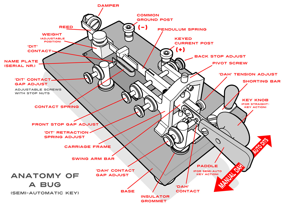
So last night I came up with an idea to break down the anatomy of one of the type of Morse code (CW) key I use which is called a "Bug" by Amateur radio operators.

This is a WWII "J-36" "Bug" (Vibroplex type) key manufactured by J.H. Bunnell in 1942. The base is a heavy piece of solid cast iron, and the rest is nickel coated brass.
The swing arm is moved one way to act as a way to make manually sent dashes "dah's" and moving the arm the other way causes a pendulum to reverberated a spring-loaded contact to produce exact dots "dit's".
The weight on the reed determines the frequency and will give you about 150 dits if needed with the default configuration yielding dots at about 40 word-per-minute speeds.
I have an added weight called a "Bug Tamer" which brings it down to 18 wpm.

This type of key was mostly perfected and mass-marketed by a company called Vibroplex starting in 1904 and is still in business today, though the concept goes back to the old telegraph days in the 1800's.

Go to this site to see a nifty Flash animation of how this key works::: http://www.ae4rv.com/tn/education/bug.htm


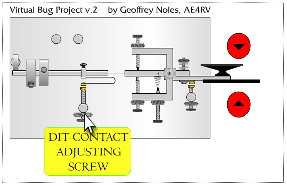
Armed with only a small engineer's ruler, I transposed the measurements into a MoI model, outputted it to a PDF, then used Corel to do the rest.

Though I could have just used the PDF result, I tend to develop certain niches with styling, and after spending two decades of hand-drawing, scanning and tracing to vector - I'm partial to the results.

Nothing too noteworthy, but a very basic result that did the job when needed.

EDITED: 1 Dec 2013 by MAJIKMIKE

  Reply Reply More Options
Post Options
Reply as PM Reply as PM
Print Print
Mark as unread Mark as unread
Relationship Relationship
IP Logged

Previous
Next
 From:  Martin (MARTIN3D)
6201.295 In reply to 6201.294 
Hi Mike, I love your Bug illustration!
  Reply Reply More Options
Post Options
Reply as PM Reply as PM
Print Print
Mark as unread Mark as unread
Relationship Relationship
IP Logged

Previous
 From:  Mike K4ICY (MAJIKMIKE)
6201.296 
Thanks Martin!!!


Hi Michael,

Did anyone forget to mention that this new PDF feature essentially gives MoI the long sought after "PRINT" button option?

I know it's obvious.

;-)
  Reply Reply More Options
Post Options
Reply as PM Reply as PM
Print Print
Mark as unread Mark as unread
Relationship Relationship
IP Logged
 

Reply to All Reply to All


Show messages:  1-3  …  224-243  244-263  264-283  284-296