New user: problems with a fillet
 1-20  21

Next
 From:  AJ (MR_A)
6150.1 
Hello.

I'm a very fresh user of MoI trial version. I find the program very fun to use and I think it would be a great if I integrated it into my pipeline.

However, today I have encountered a problem to which I cannot find any workaround. I'm not new to NURBS, but I lack experience in modelling with this kind of technique, so the problem might be just a user error from my side.

The thing I have trouble with is the fillet of all edges of a relatively simple object (a part of a hinge). It seems that my every attempt to create that fillet ends up with no fillet being created at all. I tried setting up a very small radius, but it didn't help.


On the other hand, if I select one edge at a time, and launch the fillet command, I can see that the program tries to calculate it and then shows a fillet that is obviously wrong.


The shape has been constructed using Sweep command with:
- path curve: consisting of a CV curve and a circle. The circle was cut using the Trim tool and joined with the first freeform curve to create a continuous spline.
- profile curve: which was a closed rectangle.
- boolean subtract operations: in order to cut bolt holes and to create an empty space between those curly... um... things (I'm sorry, English is my secondary language).

Can someone advise me what to do in order to create this fillet and what not to do in order to avoid the problem from occurring in the future?
I've searched the forums a bit and someone suggested to explode the model into surfaces and re-join them again. Is there a command for it, or do I have to copy/paste a single surface at a time?

Thanks in advance.

  Reply Reply More Options
Post Options
Reply as PM Reply as PM
Print Print
Mark as unread Mark as unread
Relationship Relationship
IP Logged

Previous
Next
 From:  Michael Gibson
6150.2 In reply to 6150.1 
Hi AJ, can you please also post the 3DM model file of your object instead of only a screenshot? With the actual model file it's then possible to zoom in closely to examine different areas and rotate around it, etc... it's a lot easier to see what kind of situation you have that way rather than looking only at a screenshot.

re:
> I've searched the forums a bit and someone suggested to explode the model into surfaces and
> re-join them again. Is there a command for it, or do I have to copy/paste a single surface at a time?

You can use the Edit > Separate command to break a model into individual non-connected surfaces.


re:
> Can someone advise me what to do in order to create this fillet and what not to do in order to avoid
> the problem from occurring in the future?

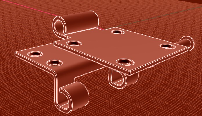
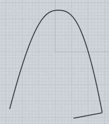
It's hard to say from looking at a screenshot alone instead of looking at actual geometry, but my best guess from just your screenshot is the problem is due to the tightly bent shape in this area of your model:


When you try to fillet something with a radius that is greater than the existing bend , it will usually fail because the fillet gets kind of bunched up and intersects itself in that zone of the model, like this:


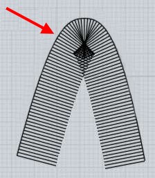
So usually you don't want to have a tightly bent shape along an area that you then later on plan on filleting with a fairly large radius value. Often times it's better to leave those areas sharp and also use filleting to produce the round in those spots too instead of having them drawn in separately before.


Also when you do the fillet, make sure you're selecting both of those edges that run along the entire length of the model there, if you only select one edge it will then make only a partial fillet that will not easily be able to figure out how to trim the main object and that will result in a partial fillet result like you show in your screenshot. That happens when there was some problem in one of the later stages of the fillet process like with trimming the model but some of the previous steps for the calculation of the fillet surfaces themselves were successful - the partial fillet results are returned to you in that case so that you might have a chance of trimming them into place yourself manually. If you hide your main object you should see that the weird looking fillet that you get is actually a separate rounded surface which is just submerged into the object.

You may be able to use the Trim or boolean commands with that piece to get the fillet into place, if you can post the 3DM model file that would make it easier to try and help you to do that.

- Michael

  Reply Reply More Options
Post Options
Reply as PM Reply as PM
Print Print
Mark as unread Mark as unread
Relationship Relationship
IP Logged

Previous
Next
 From:  AJ (MR_A)
6150.3 In reply to 6150.2 
Thank you for your response Michael.
---
>> "Hi AJ, can you please also post the 3DM model file of your object instead of only a screenshot? With the actual model file it's then possible to zoom in closely to examine different areas and rotate around it, etc... it's a lot easier to see what kind of situation you have that way rather than looking only at a screenshot."
---
Yes, I can do this. Thanks.
You will find three main solids in the scene named: roller, longer and shorter. Only on "shorter" I cannot apply the fillet. There are also some shading problems on one side of the "roller".
Attachments:

  Reply Reply More Options
Post Options
Reply as PM Reply as PM
Print Print
Mark as unread Mark as unread
Relationship Relationship
IP Logged

Previous
Next
 From:  Frenchy Pilou (PILOU)
6150.4 In reply to 6150.3 
Works fine for me! :)
I move the pieces before and fillet piece by piece

Fillet : 0.3

  Reply Reply More Options
Post Options
Reply as PM Reply as PM
Print Print
Mark as unread Mark as unread
Relationship Relationship
IP Logged

Previous
Next
 From:  BurrMan
6150.5 In reply to 6150.4 
Hi AJ,
There is a hard edge in the hinge that will interfere with the fillet when trying to make a small little patch for that area.


Here's a 3dm file of the part where I cut out the cusp and made a smooth transition for it, and you should be able to fillet it at the value you want.
Attachments:

  Reply Reply More Options
Post Options
Reply as PM Reply as PM
Print Print
Mark as unread Mark as unread
Relationship Relationship
IP Logged

Previous
Next
 From:  Frenchy Pilou (PILOU)
6150.6 
Aaaah yes : that was a very tiny tiny difference!
I had not my glasses on the nose!
  Reply Reply More Options
Post Options
Reply as PM Reply as PM
Print Print
Mark as unread Mark as unread
Relationship Relationship
IP Logged

Previous
Next
 From:  Michael Gibson
6150.7 In reply to 6150.3 
Hi AJ, it looks like Burr has that fixed for you above, thanks Burr!

It tends to be difficult on the filleter when surfaces are almost smooth to one another but just barely not smooth like with a shallow sharp corner like you've got there.

Any time you have edges that meet at a sharp corner it means the fillet surfaces will not directly touch each other, instead the fillets have to be cut with one another and a corner juncture patch put in. But that process is much more difficult in very shallow angle places, there is more like a region of overlap between the fillets instead of a crisp intersection and also the corner patch tends to be a little tiny slivery thing.

It's best for areas like that to be either fully smooth or more distinctly sharp instead of something like 5 or 10 degree angle between the meeting pieces.

- Michael
  Reply Reply More Options
Post Options
Reply as PM Reply as PM
Print Print
Mark as unread Mark as unread
Relationship Relationship
IP Logged

Previous
Next
 From:  AJ (MR_A)
6150.8 In reply to 6150.5 
Thank you very much guys for your help and valuable information. This is a very friendly community.

However, I still have a problem of... a weird nature. Looks like now I can apply a fillet on that object with a sharp corner from the scene I attached to my post (even though I couldn't do it before!), but the fillet does not compute for the object fixed by BurrMan. I'm very confused about what is going on. I think I must be doing something terribly wrong.

What I do is I open the hinge_cusp.3dm file, select the object, select the fillet command, enter the radius (0.3) and nothing happens. There's no "Calculating..." message or anything. The fillet is not created after I press "Done".
  Reply Reply More Options
Post Options
Reply as PM Reply as PM
Print Print
Mark as unread Mark as unread
Relationship Relationship
IP Logged

Previous
Next
 From:  Michael Gibson
6150.9 In reply to 6150.8 
Hi AJ,

> What I do is I open the hinge_cusp.3dm file, select the object, select the
> fillet command, enter the radius (0.3) and nothing happens.

It looks like those steps work ok in the current v3 beta, but not in the v2 version which is the version for the trial.

I've attached here an updated version of the model which should work for you in v2 as well as v3. For this version I deleted the "side walls" that were made up of 3 coplanar pieces and then used Construct > Planar to build just one big trimmed plane in those spots instead of 3 coplanar fragments.

Sometimes the filleter also doesn't like to have multiple coplanar fragments next to one another instead of one big single planar surface, but in this case it's been fixed up in the more recent v3 versions to work.

- Michael
Attachments:

  Reply Reply More Options
Post Options
Reply as PM Reply as PM
Print Print
Mark as unread Mark as unread
Relationship Relationship
IP Logged

Previous
Next
 From:  AJ (MR_A)
6150.10 In reply to 6150.9 
Ah, so this was the problem. I'd have never figured it out on my own.
Thank you very much Michael - fillets finally compute properly.

Now I can proceed with further exploration of MoI. :)
  Reply Reply More Options
Post Options
Reply as PM Reply as PM
Print Print
Mark as unread Mark as unread
Relationship Relationship
IP Logged

Previous
Next
 From:  AJ (MR_A)
6150.11 In reply to 6150.5 
Hello again.
I have a question for BurrMan.
May I ask how did you cut out that sharp corner? I'd like to reproduce steps you've done to accomplish that.
  Reply Reply More Options
Post Options
Reply as PM Reply as PM
Print Print
Mark as unread Mark as unread
Relationship Relationship
IP Logged

Previous
Next
 From:  BurrMan
6150.12 In reply to 6150.11 
Hi aj,
I went to the side view and drew a square that enclosed the whole area, then did a Boolean diff. Then delete the faces of the 2 pieces facing each other so they are open. I ran a blend on the top and bottom, then did a 2 profile, 2 rail sweep on the sides to be able to join it back into a solid.

If that's not clear, I can make a quick video.
  Reply Reply More Options
Post Options
Reply as PM Reply as PM
Print Print
Mark as unread Mark as unread
Relationship Relationship
IP Logged

Previous
Next
 From:  AJ (MR_A)
6150.13 In reply to 6150.12 
Thank you BurrMan.
I've managed to repeat your steps and learn something new. I didn't know that you can cut solids using curves, even in 3D view. Very useful.

Oh, I forgot.
What if I need to readjust the fillet after it has been created? Is it possible to remove it and recreate it without having to create the object from scratch?

EDITED: 4 Sep 2013 by MR_A

  Reply Reply More Options
Post Options
Reply as PM Reply as PM
Print Print
Mark as unread Mark as unread
Relationship Relationship
IP Logged

Previous
Next
 From:  Michael Gibson
6150.14 In reply to 6150.13 
Hi AJ,

> What if I need to readjust the fillet after it has been created? Is it possible to remove it
> and recreate it without having to create the object from scratch?

It is possible to delete the fillet and then do some untrimming and retrimming of the surrounding surfaces. There is a tutorial on those object repair techniques here: http://moi3d.com/forum/index.php?webtag=MOI&msg=446.17 . But it's still a fair amount of work involved so it's generally better to save off an unfilleted version of your object to a separate file so you can go back to it later on.

If you think you're going to need to do a lot of edits like that you may want to use what is called a "parametric history based" CAD program like SolidWorks or Alibre which are focused on keeping a list of actions that can be edited. MoI is more focused on making it as easy as possible to just freely draw and create the initial models.

- Michael
  Reply Reply More Options
Post Options
Reply as PM Reply as PM
Print Print
Mark as unread Mark as unread
Relationship Relationship
IP Logged

Previous
Next
 From:  AJ (MR_A)
6150.15 In reply to 6150.14 
Thank you Michael and I apologise for my late reply.
No, I don't think that I'd require many edits, so keeping hidden backups of non-filleted solids seems to be enough for me. I'm thinking of using MOI to create quick prototypes of hard surface models that I will later use as base models for voxel sculpting and/or retopologise them for subdivision.
  Reply Reply More Options
Post Options
Reply as PM Reply as PM
Print Print
Mark as unread Mark as unread
Relationship Relationship
IP Logged

Previous
Next
 From:  Will (ALTAIC)
6150.16 In reply to 6150.15 
Hi Michael, I run into these issues pretty often, and it occurred to me that a really useful feature would be visual feedback indicating the problematic edges. A status/error pane/bar would also be really nice, since stuff seems to fail silently-- additionally, since some actions automatically complete without hitting done, silently failing can be a bit bewildering.

Will
  Reply Reply More Options
Post Options
Reply as PM Reply as PM
Print Print
Mark as unread Mark as unread
Relationship Relationship
IP Logged

Previous
Next
 From:  Michael Gibson
6150.17 In reply to 6150.16 
Hi Will, the problem is that it tends to be quite difficult to provide error information that makes any sense to a regular human being as opposed to a mathematician...

It also requires some cooperation from the inner functions of the geometry kernel itself to return back the specific information about what particular edges caused the problem, right now this is not really provided for in an extensive way by the geometry library that MoI uses.


> additionally, since some actions automatically complete without hitting done,
> silently failing can be a bit bewildering.

Do you have an example of one of these situations? It always helps to have a specific example to look at rather than just talking in general terms.

There are many commands that don't have any further options to adjust in them, those generally finish without needing to do a separate additional "Done" stage in order to increase efficiency of operation.


At some point I would like to have a kind of console area where a log of information could be displayed. I have not yet found a good place to put that in the UI without it consuming a lot of space and kind of dominating the UI to a problematic extent though.

- Michael
  Reply Reply More Options
Post Options
Reply as PM Reply as PM
Print Print
Mark as unread Mark as unread
Relationship Relationship
IP Logged

Previous
Next
 From:  Will (ALTAIC)
6150.18 In reply to 6150.17 
Hi Michael, I suggested the visual feedback (perhaps highlighting problematic edges in red) to avoid complicated error messages, though if an command fails, it would be nice for the command pane (top left corner) to at least display "command failed" or "union failed" or some such instead of just disappearing.

As far as commands which sometimes do not require pressing "done" go, most recently I ran into a bit of frustration unioning complex solids which I had preselected. I eventually reworked the solids, but the bewildering bit is this: the union takes a long time, and the "done" button still responds to clicks, but does not appear to do anything-- then the command pane disappears and I assumed the union had succeeded. I only discovered that it hadn't after trying to do another boolean operation where one of the failed union pieces was hidden from view. I retried the union a few times before I realized it was not operator error in applying the union, but that my model was broken in some way.

Will
  Reply Reply More Options
Post Options
Reply as PM Reply as PM
Print Print
Mark as unread Mark as unread
Relationship Relationship
IP Logged

Previous
Next
 From:  Michael Gibson
6150.19 In reply to 6150.18 
Hi Will,

> though if an command fails, it would be nice for the command pane (top left corner) to at least display
> "command failed" or "union failed" or some such instead of just disappearing.

That's already been added in for the most recent v3 beta. From the release notes:

quote:

Implement "Calculation failed" UI similar to the "Calculating..." message, but that is displayed if there was no output generated. Requested on the forum here: http://moi3d.com/forum/index.php?webtag=MOI&msg=5803.1 .


> As far as commands which sometimes do not require pressing "done" go, most recently I ran into a
> bit of frustration unioning complex solids which I had preselected.

Yeah that happens because it's also possible for Union to work with nothing initially selected in which case it asks you to select things and waits for you to push "Done". That same UI is ending up displaying for the preselection case as well. I guess that could be tuned up by hiding the "Done" button for the case of stuff having been already preselected before running the command.

The new "Calculation failed" UI should be helpful for distinguishing cases where there was not any result generated, although with boolean union there is another complication with failures in that it's not quite the case that nothing is generated from the union but that the same objects are generated out the other end but they did not cut each other up.

- Michael

EDITED: 15 Sep 2013 by MICHAEL GIBSON

  Reply Reply More Options
Post Options
Reply as PM Reply as PM
Print Print
Mark as unread Mark as unread
Relationship Relationship
IP Logged

Previous
Next
 From:  Will (ALTAIC)
6150.20 In reply to 6150.19 
Ah, I didn't realize the new beta added that. Excellent!

I know the preselection causes automatic command execution for some commands, which is great. It was just baffling when the command pane appeared and suddenly vanished without completion for no apparent reason. Anyway, the new UI you mentioned should help with that.

As a suggestion for the done button, perhaps when the command starts execution, change the text to "Calculating..." and disable the button so it doesn't respond to clicks.

Edit: Actually, an approach more consistent with typical UI would be to immediately change the entire content of the pane to a progress view. Even if a progress bar or percentage is not doable and it just displays "Calculating..." and a cancel button, the content switch makes sense. Usually one expects clicking done or cancel to immediately close the pane or transition to a new content view. Just my $0.02.

Will

EDITED: 18 Sep 2013 by ALTAIC

  Reply Reply More Options
Post Options
Reply as PM Reply as PM
Print Print
Mark as unread Mark as unread
Relationship Relationship
IP Logged
 

Reply to All Reply to All


Show messages:  1-20  21