With contact or without it doesn't affect this thing that I'm asking about)
What method you use to discovery contact point or not? I use trim if dot appears than there is contact)
Hi mir4ea, that kind of shaping happens when different length pieces are kind of rushing towards one another and collapsing down to a single point.
It can be better to build something with a tight bend in it like that as initially flat instead and then use filleting to round off the tight bend, rather than trying to directly surface the bend itself.
m-dynamics, thanx good alternative)
Michael, thanx for your answer, but I am not sure I understand you right)
Could you pleas make some screens or tell in another words, thanx)
Hi mir4ea, first a bit of explanation on why you get that kind of shape in the first place - imagine instead if you had a sharp cornered profile and you wanted it to collapse down to a point in the same way, that would look like this:
So notice there that the corner takes a sort of diagonal trajectory as it collapses down into a single point - basically features of your profile curves follow that same kind of trajectory as they approach that point, it can then be pretty natural for some evidence of that path to be present in the resulting shape.
It seems that the main thing that you're trying to build has some broadly shaped areas like this:
Then in between those broad areas you want some more tightly curved transition areas in these areas:
So usually in NURBS modeling tightly curved transitions between areas are done with fillets - currently you're basically trying to directly model both the broad shapes and the transition shapes all at the same time, and that can work ok in some spots but it's difficult to make it work very well in spots that collapse down to a point because of the shaping issue that I described above. So for that end it could be better to put a fillet on that one area rather than trying to construct it directly. That would go something like initially draw a flat ended shape, and then if you don't want a totally flat end, model a curved end cap using revolve or sweep (here I've used sweep), then cut off the end of your shape with the curved end cap and now you have the end curved form and then apply a fillet on the edge shown to make the transition:
Hi mir4ea, I would myself probably go with the filleting method, just because it can generally be difficult to control the surface shape in pinched-down areas.
But it also depends on what in particular you want to control - the filleting method lets you control the end cap shape more easily since you can build a more simplified surface for it but you are relying on filleting to generate some pieces for you instead.
In the end, there is not any "one absolute right way" to do stuff, it can sometimes just depend on your personal preference.
Just in general though I find it difficult to get good surface quality when you're trying to force the surface through too many different shapes all in one single surfacing attempt. So building some broad forms separately and using fillets for transitions can tend be good instead of trying to model them all at once.
Also if you need to make a model that is sort of blobby / melted looking stuff like that can tend to work better in a sub-d modeling program rather than in NURBS.
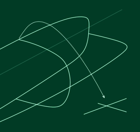
Regarding French's response in which he pointed out that the sketches do not actually intersect.
Can someone post how to fix this in MoI (rotating into place and scaling, or aligning, or whatever approach works best). I have not run into this issue as I use snaps both in Rhino and MoI. In the event that I have to use traditional CAD tools I constrain all my sketches. I know how to fix issues like this in other programs, but in Rhino & MoI I have not run into this as I use the snaps. Repairing the sketch issue would be a great thing to know (with an image or three to help my visual brain).
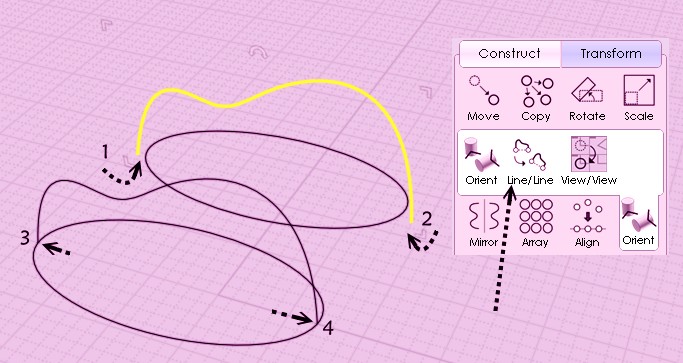
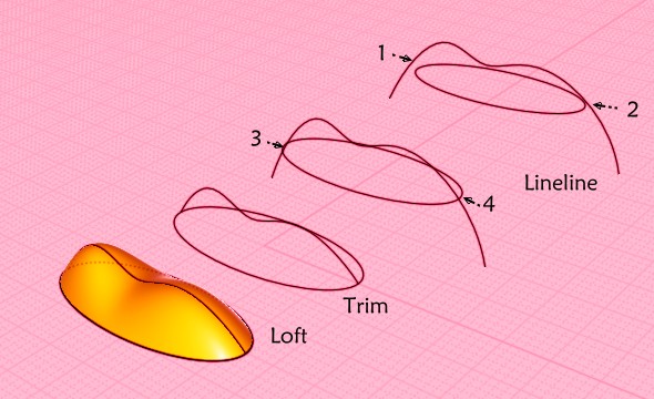
My favorite tool! The Line Line on the Curve selected! :)
Just 4 clicks! And you can choice Uniform, Strech or None! Copy or Not! (here the None's case never works because ellipse's size is smaller than the biggest size of the curve )
You can of course make clicks 1 & 2 anywhere on the curve following wished result! Above it was curve's extremities
heere it was along the curve!
PS Ellipses are similar (just perspective's effect ! ) Curves are different in x,y or x,y,z following Stretch or Uniform
You can have a same result with the "Edit Frame" (you can see its handles on the image) but it's less practical in some cases!
Select / Move/ Adjust Axe of Symmetry / Rotation / Adjust on X, / Adjust on Y / Adjust on Z etc...
Nice! Definitely one technique to add to the ol' toolbox.
Reminds me of using align in AutoCAD years ago. You could move, align, scale at the same time. Was very handy moving sketches around and resizing them. I just need to mess around in Rhino now to see if their solution is as easy in MoI.