Majik Tutorial: Stacking School Chair
 1-20  21-40  41-43

Next
 From:  Mike K4ICY (MAJIKMIKE)
5893.1 
Well it's been a while since my last tutorial and all I needed was a little time and some inspiration...

In the recesses of my mind lies a mental list of everyday household objects I would like to someday model in Moi3D.
A few decades ago, the everyday plastic stacking school chair was one of those objects kids, like myself then, were pretty much relegated to pondering (design-wise)... it was there everyday and you, plus all your friends had to sit in them.

But you say: "it's such a mundane and ubiquitous piece of cheap furniture... it's not like it's a Marc Held or Herman Miller Aeron chair worthy of gallery parties and exhibitions."

No, it's a VIRCO.

Something must be great about this chair's design!
For starters: VIRCO MFG Corporation (www.virco.com) has produced literally millions of the "9000 Series" for use in thousands and thousands of school systems, churches and civic gathering centers all over the world for decades. It's extremely durable, easy to repair and many of them can be stacked vertically to save precious classroom space.
At just a few components, the chair consists of a polypropylene moulded plastic shell and a steel tube frame that is spot-welded and reinforced. Simple.
True masterpieces of industrial design are those that endure the test of time, and for one of two reasons: 1) They're well designed or 2) Well marketed. So maybe both.

I will show here how a plastic stacking school chair can be modeled in Moi3D.

When I started this tutorial, I didn't even know who manufactured these types of chairs, I was simply going from memory.
With that, I'll not be using any real-world measurements or proportions and will not be building this model with manufacturing techniques in mind.
This model is not an exact reproduction of the VIRCO chair, just a fun exercise.

But with my tutorial, hopefully you should be able to better realize some of the useful tools and methods available in Moi3D.
You should be able to apply some of the techniques to different designs and looks.


Here's the chair:


I spent a week or two actually trying different techniques to attempt the form of the plastic shell.
Myself, the master of Networks and Blends ran into a little difficulty.
Though, deceptively simple, the shell is actually a complex shape!

Not only is there a lip of varying depth that runs around the perimeter, but there's a contour and subtle curvature to the seat and back.
Plus, there are these back vent holes and I also wanted to simulate the warping of the plastic near the large rivet holes.


Let's make this shell with a two-step processes; a "mechanical" and "organic". This way, we can better manage the result.


If you imagine the shell flattened out from it's "L" shape, you can use a few Polylines or curves to define the sides.
The middle C-plane line, half way up can represent the area just below the lumbar.


You can do everything on one side and then mirror a copy if you like, but sometimes it's easier to just to build both sides.


Well build in some 3-point arcs to complete the shape. The bottom arc is for the edge of the chair under the knee-bend, and so forth.


A "G2" Fillet of the corners will give the body a nice form.


Larger fillets can be used to give a sweeping shape to the angle change on the sides.


Now it's time to make the 'vent' holes for the back of the shell. This is really not a necessary feature from an engineering standpoint,
except that it does add an amount of stress-support with the structural 'ribs' acting as the sides of the openings.
Each company uses it's own pattern, whether it be circles, triangles or squares, and the particular design is a patented and copyrighted feature of their product.

Inspired by the Virco model, we'll arrange three rectangles with rounded corners and place the bottoms of the shapes a little below the center line.


Lets make some small circle to represent the holes for the connecting rivets.
Place the two up top to tie in a support bar. The two bottom ones on the seat should be placed so that the frame tubes tied to them can run freely around the back vents.


Just select everything, provided it all lies within the same plane, and Extrude your shapes into one monolithic solid.


Fillet the solid.


We're now going to simulate the dimples made by the compression of the rivets through the shell to the frame.
I used the largest Fillet allowed in this instance.

As shown here:


Now, unless the shell plastic is really thick, we'll need to compress the (Z) depth of the Fillet surfaces.
Separate them from the main object and use Scale 1-D to squish them upwards.
Join them back to the main body compound object once done.


If you notice from the example diagram shown, the thickness, or depth, of the edge lip varies depending on where it is along the body.
Simply make a curve to represent the profile. Keep in mind to carefully place the deepest part where, once bent into form, will cause this area to be where you want it. Don't be afraid to go back 'to the drawing board'.


A Boolean Difference can be done to form the edge profile.


Use some skill :-) and trim the inside vent parts a little more recessed than the main edge lip.


I'm not going to mince words here... The NURBS Library may fail you here:
It's time to the Shell tool or Offset the remaining joined-surface set to give the part some perceived thickness.
It worked sometimes in my experimentation and not in other instances. Just do the best you can.


Here, I use a little personal touch; since I used the Shell command to make an adjacent surface, I Blend the edges together to make a nice round-over.
As you can see here, I 1-D Scaled in the inner surface so that it gave me a nice angled bevel. Though you don't have to use this step.


I just join the inner and outer surfaces, plus the blends, and it looks nice.


Now we should be done with the "mechanical" portion of the chair-shell form.

We were able to produce everything on a flat and manageable form that allows us to go back and make alterations if need be.
This would be very difficult on a more complex Network type form.


We'll need to build some profiles to represent the basic form of the seat and back itself.

In this example the red curve represents what I want the middle of the chair to do. The blue curves will be the sides.


Next: without regard to literal placement, I'll need to create several symmetrical profiles to represent 'what' the chair form is doing at different stages as you move from the knee-area to the upper back.
It is important to make sure that if you create a mirrored profile that the connecting points are 'tangent'.


Use the Orient tool to organize these profiles in their appropriate positions. Go to your side views and adjust where necessary.


Now make a Network surface from your profile matrix. Please note that the end points of the inside profiles should actually touch along the outer profiles. Network will often have issue if not set up tight enough.
You'll now have a form to represent the "organic" part of the shell form.


[You'll need Moi V3 from here on out]

Using the new V3 Flow tool, first create a 'reference' plane. Place it somewhere in the middle of the 'mechanical' form.
Please note that you should not use a square that you performed Planar on or the points will be in the wrong place. Just use the Plane tool.


Use the Network surface as the Flow 'target'.
Here you go!


Here is the final chair shell form - which represents 80% of the work on this model... ;-)

EDITED: 16 May 2013 by MAJIKMIKE

  Reply Reply More Options
Post Options
Reply as PM Reply as PM
Print Print
Mark as unread Mark as unread
Relationship Relationship
IP Logged

Previous
Next
 From:  Mike K4ICY (MAJIKMIKE)
5893.2 In reply to 5893.1 
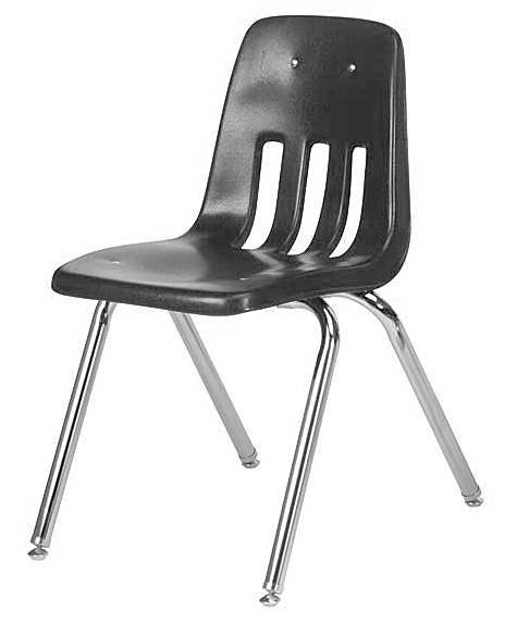
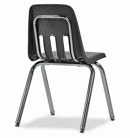
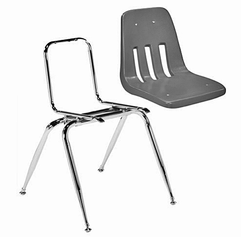
This particular chair has a steel frame that provides support for the both the chair back and the legs.
Since the plastic shell is flexible, it requires this support.
Other similar types of chairs may employ a combination of structural ribs and metal lumbar braces to achieve the same stability.


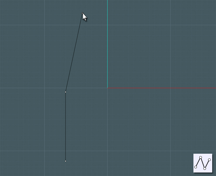
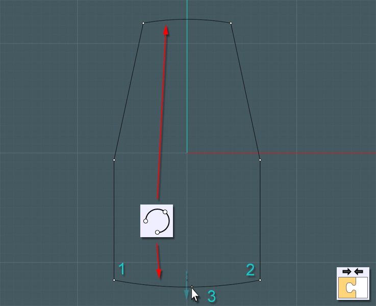
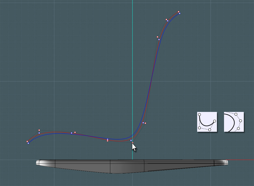
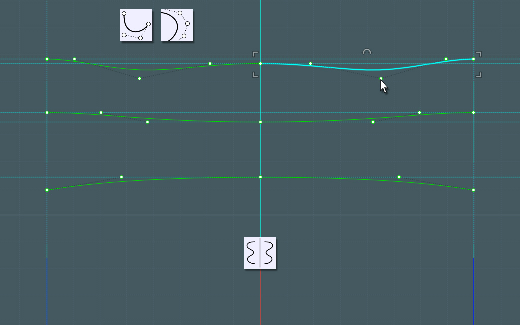
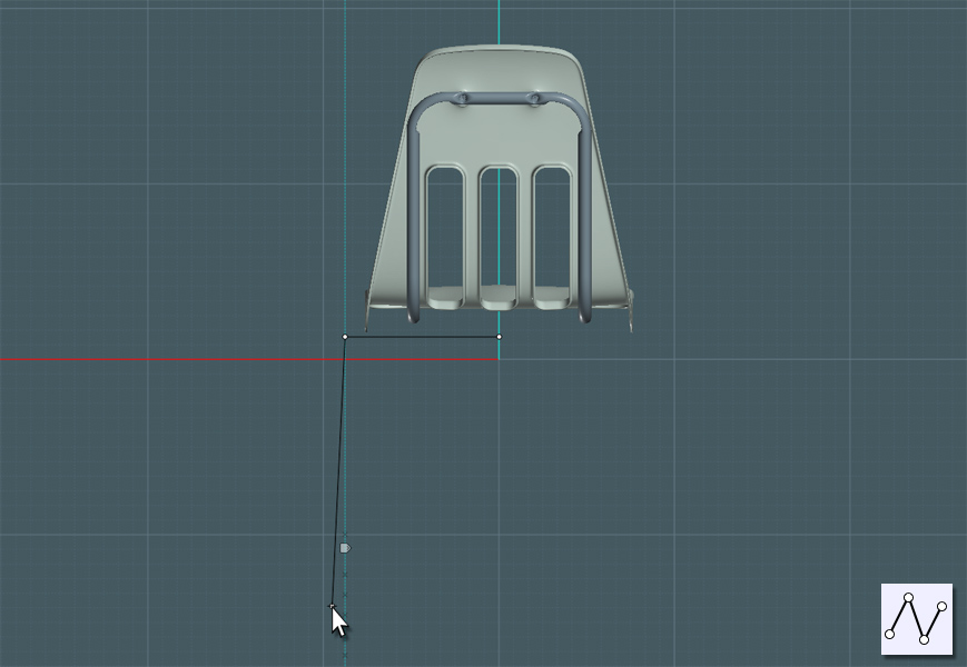
Draw a line that will represent the rise of the back part of the shell frame.
The frame will consist of a single length of steel tubing that is bent in several places to run the course around the shell.


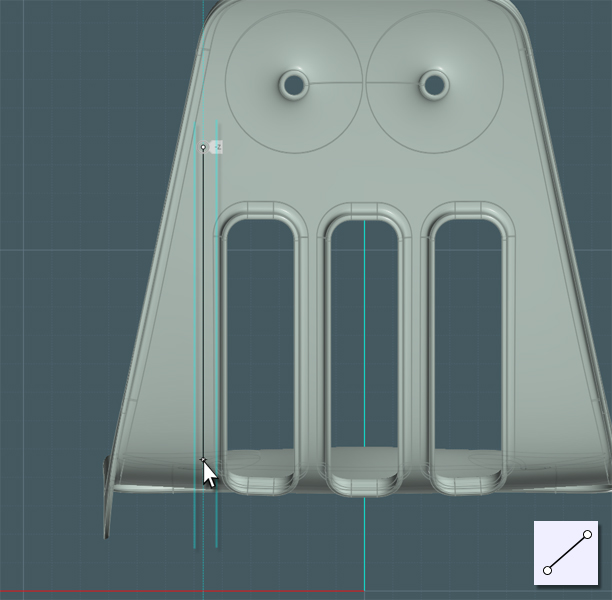
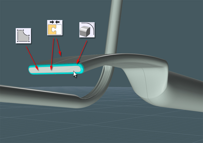
Make a line to represent the top.


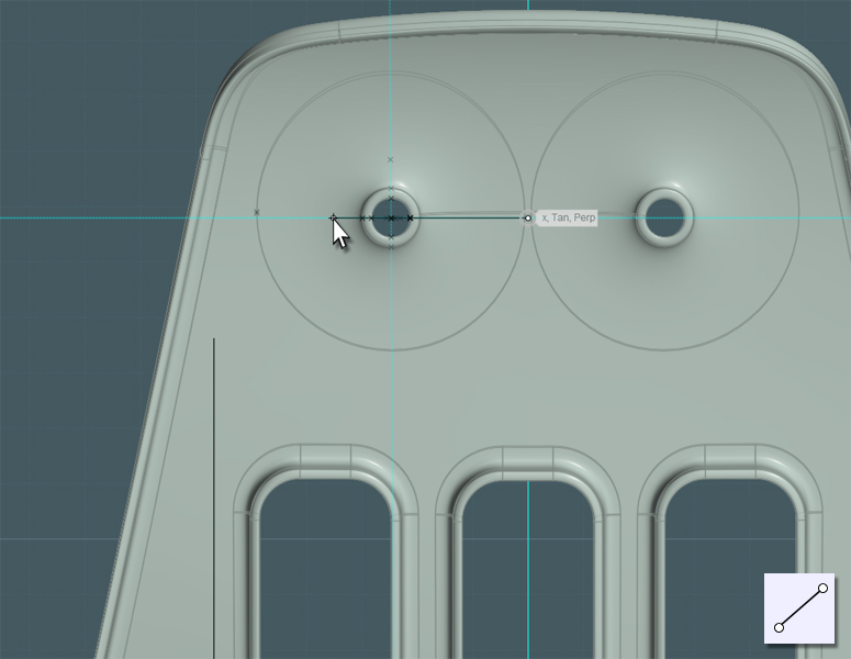
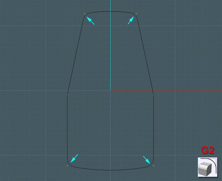
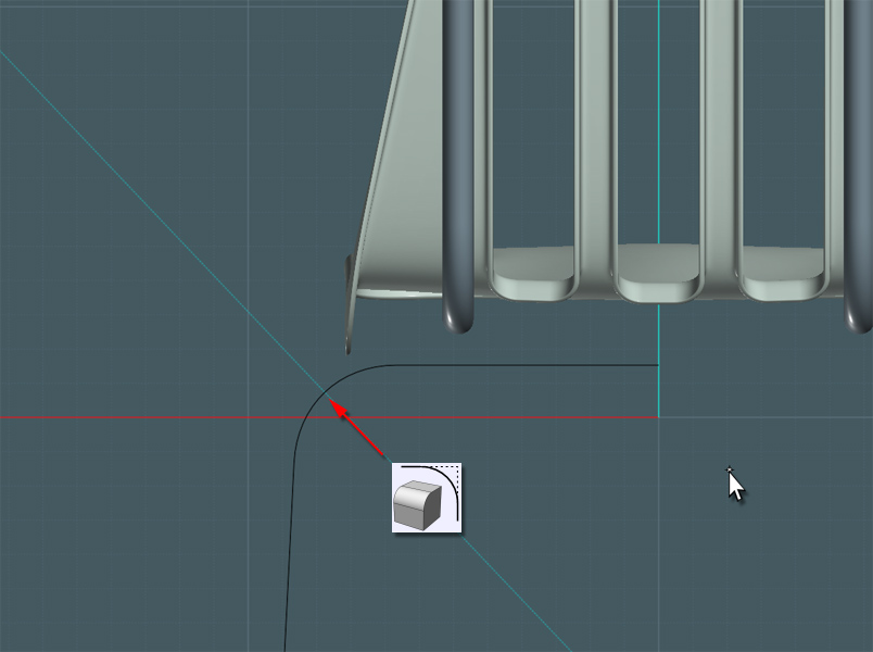
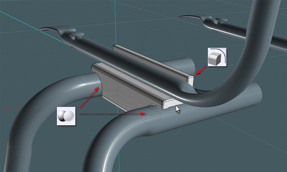
Use the Blend tool to create a fillet for the top of the frame... or simply Fillet a box.


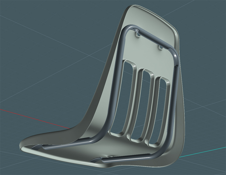
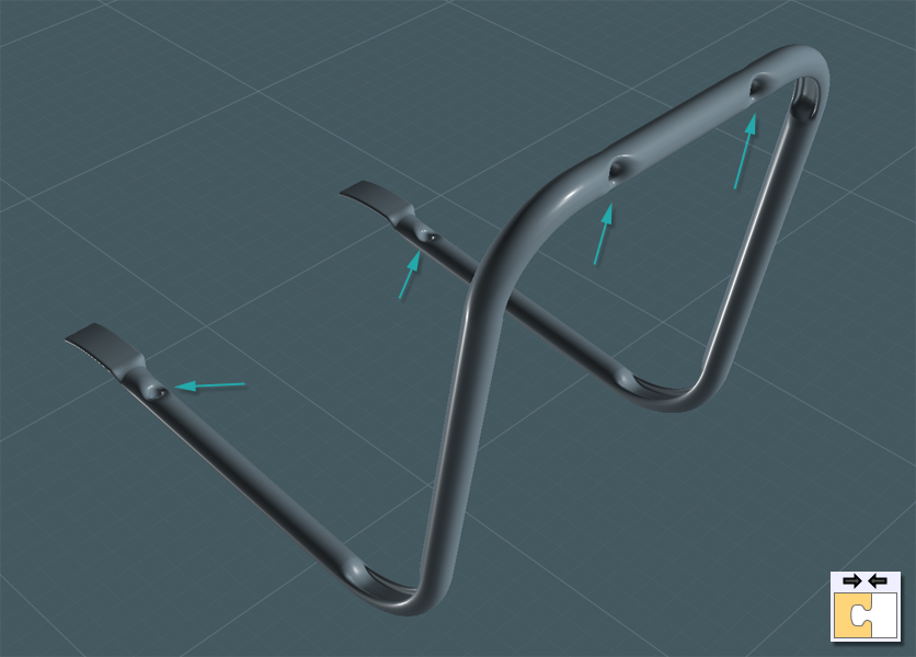
Here is an example of the chair's frame structure:


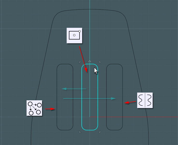
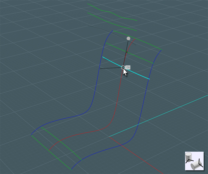
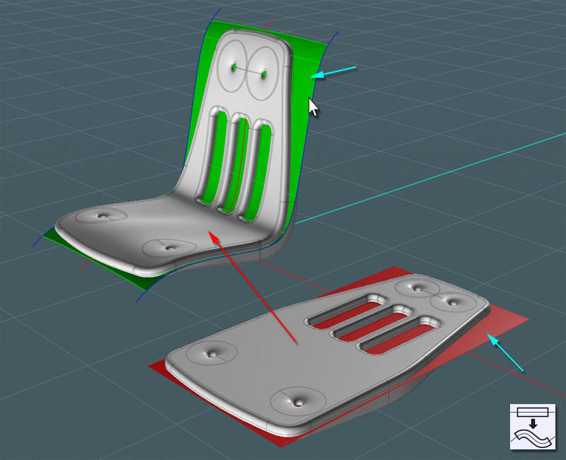
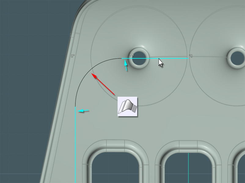
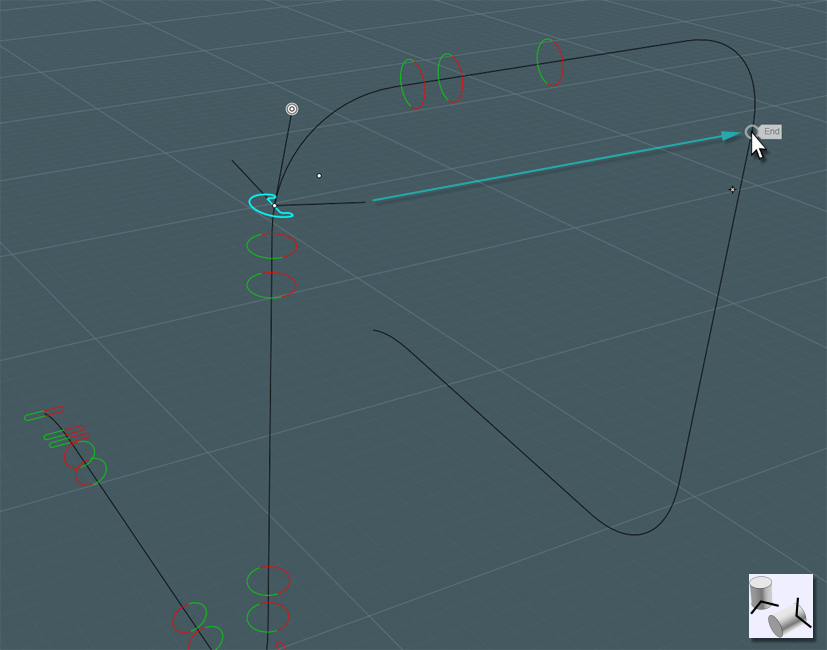
I need to have some way to know where to route the path for the frame.
The shell is pretty complex, so for accuracy I Projected a few lines on the shell form to give myself an idea on where to place the frame.


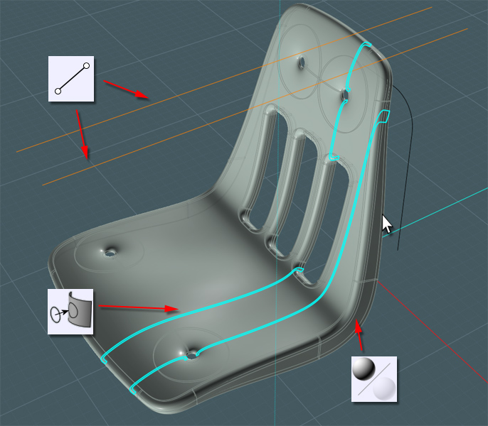
In a side-view I'm now able to complete the bottom part of the frame using Lines and Blends. Join all.


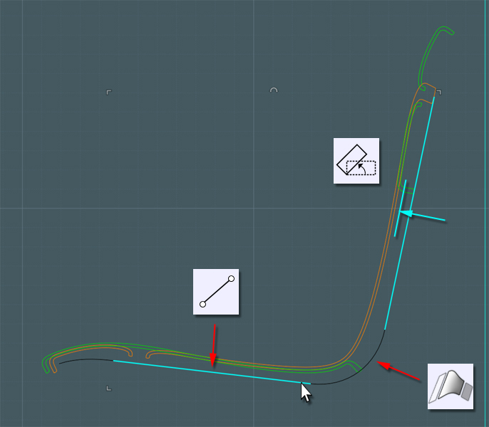
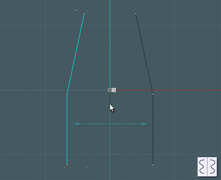
The frame is symmetrical so I Mirror the path.


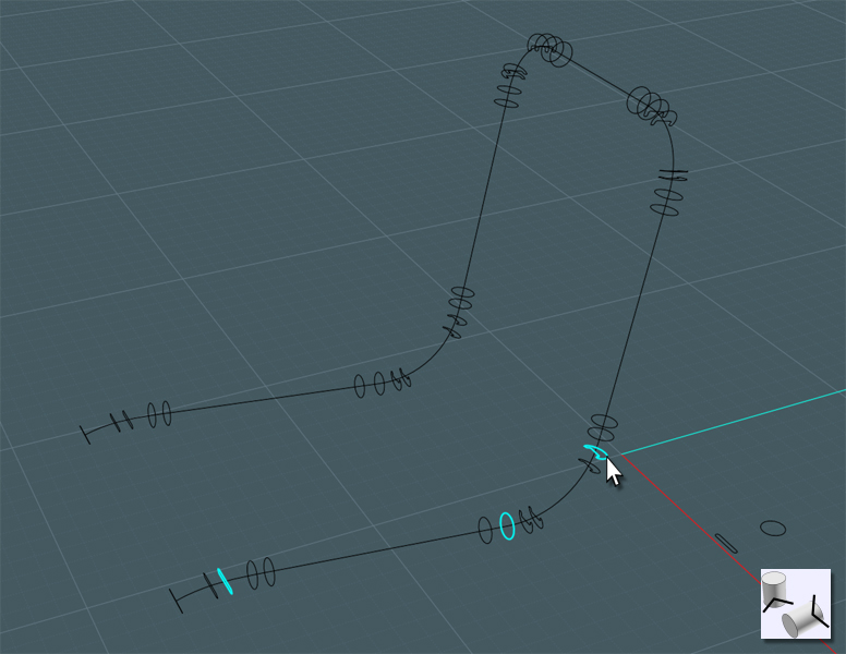
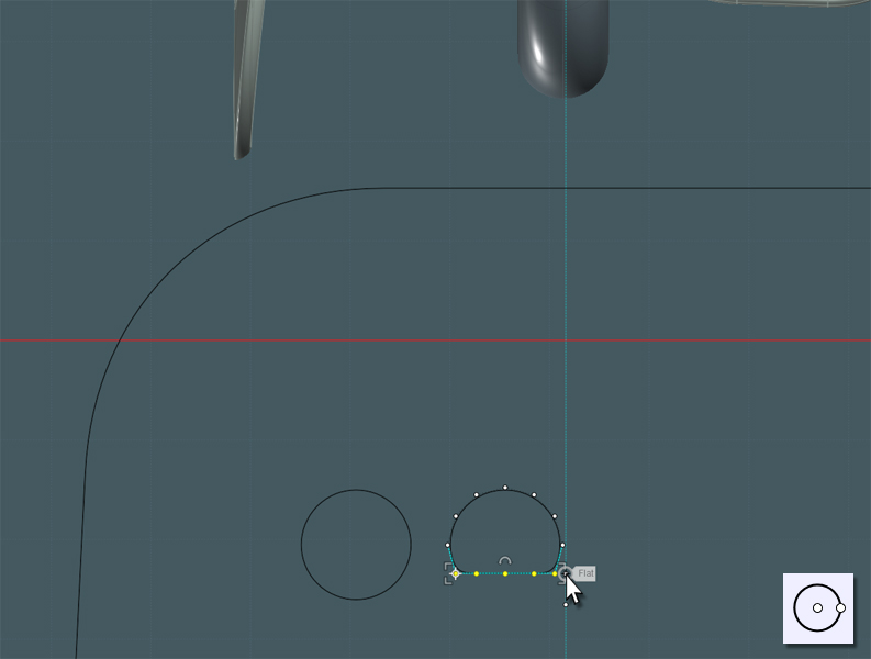
To make the frame tube, I'd like to use a few profiles to represent where the tube is round and where it has been bent using machined creases.
The creases add structural support with their "I beam" shapes as well as preventing the excess area of metal from crumpling once compression forces are applied in the bending process.


Using the Orient tool, I place these profiles in appropriate areas along the frame path.


Each profile shape represents what a Sweep will do once applied to the path.


OH NO... Moi! "The Sweep tool - not the sausage-link tool!"

It appears that the Sweep tool lacks the ability to reliably negotiate the 'normal' orientation and 'start-point' of the profile curves.


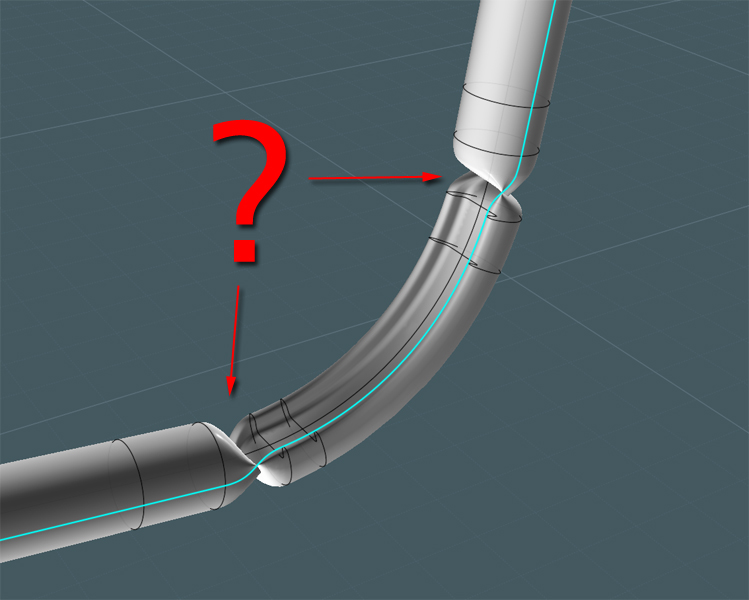
Back to the drawing-board...

Let's try another approach:
We'll do this in two controllable Sweeps using a common path!

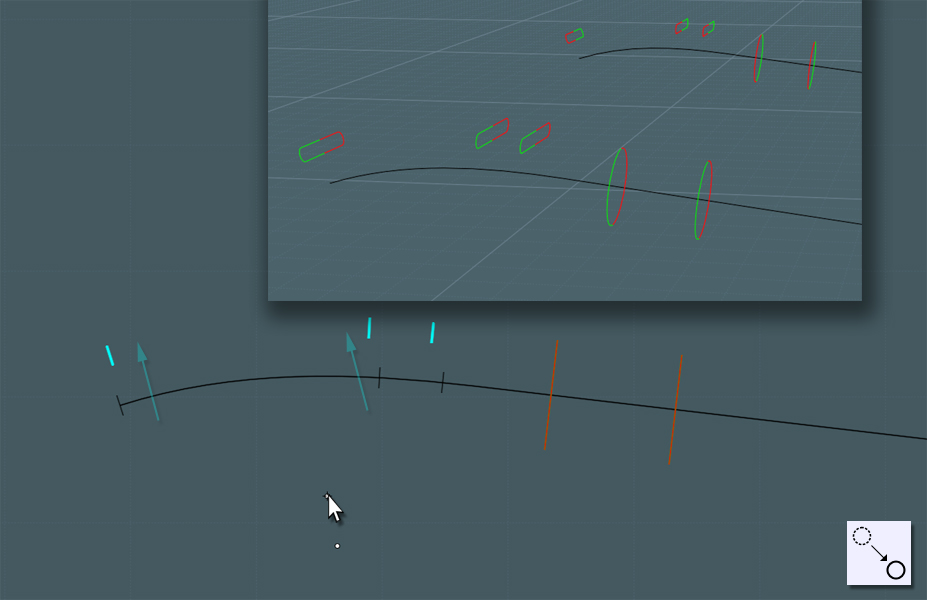
Use Trim to cut your profiles in half. The "bendy" profile at the top has been turned to the side as it represents the tube which will be bent at a different orientation that another part of the same tube... I colored each half for visibility.


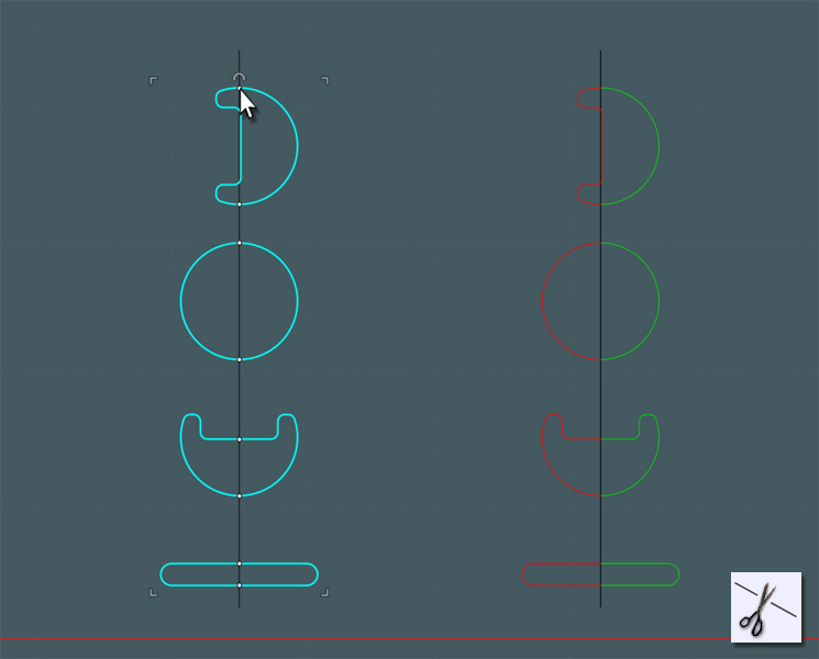
Don't worry about the color here we'll just orient each profile (set) where we need them.


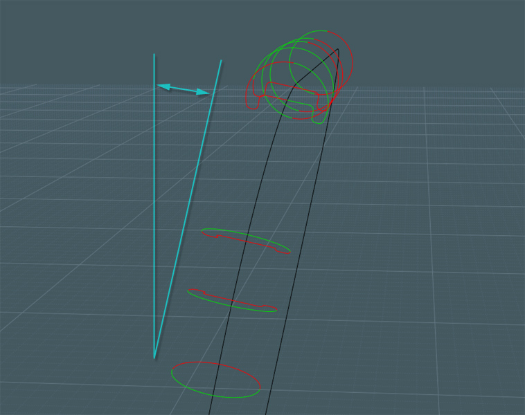
Please note that since the tube is set at an odd angle, the orientation of the profiles need to follow suit.
When using the Orient tool, once set in position along the path, use the snaps along the opposite side of the path to help control orientation.

(sorry if this is confusing... It took me a while to figure this out)


Just mirror the profiles when set.


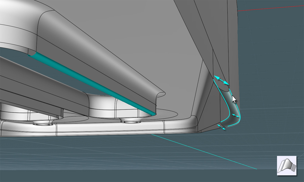
A clever engineering trick was used at the ends of the frame tube.
The ends were pressed flat to both cap the ends as well as serving as a springy support for the knee area of the chair's shell.


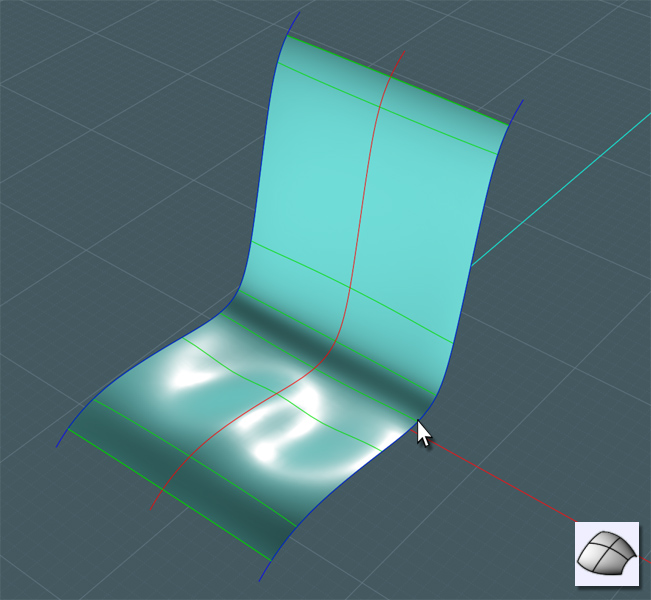
Now Sweep half of the profiles.


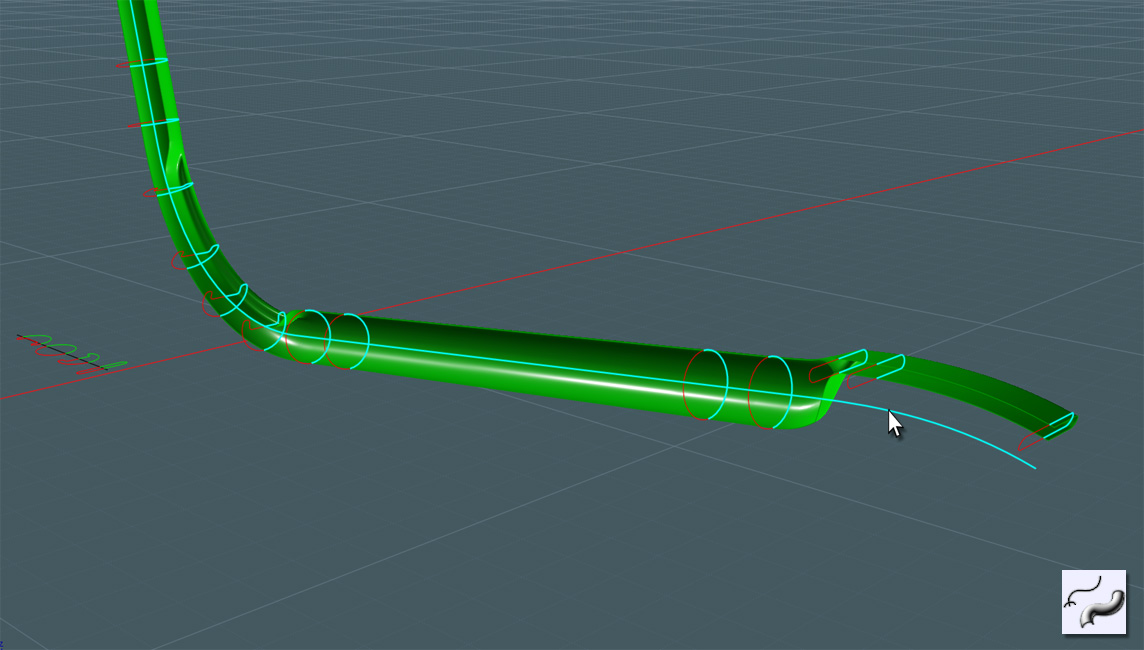
Sweep the counterpart side and Join them together. Now we have a great measure of control here.


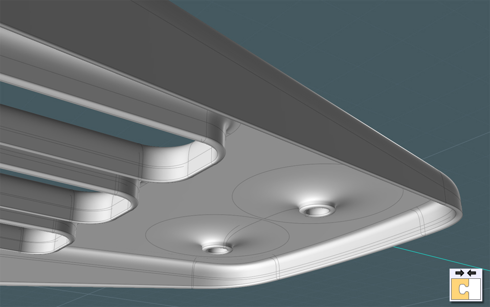
To make this a solid, I capped the ends with Planar and added a nice Fillet.


Adjust the new frame shape to more accurately fit the shell form.


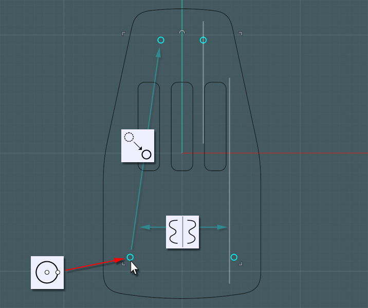
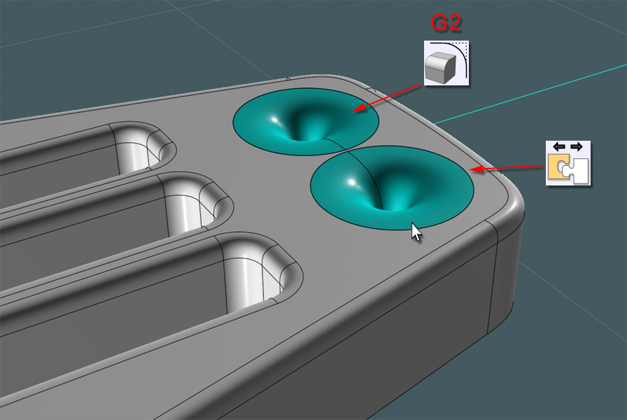
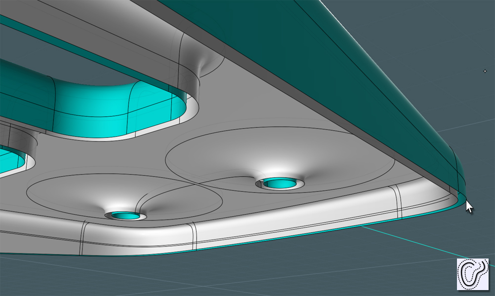
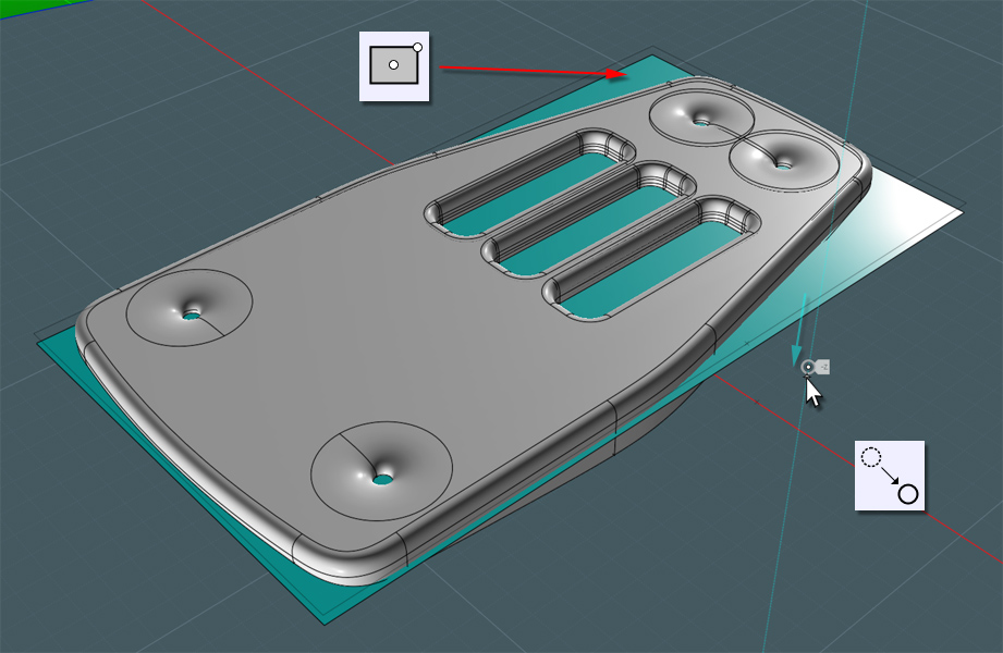
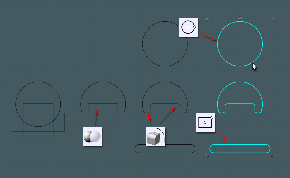
Lets add the dimples which hold the rivets through the shell.
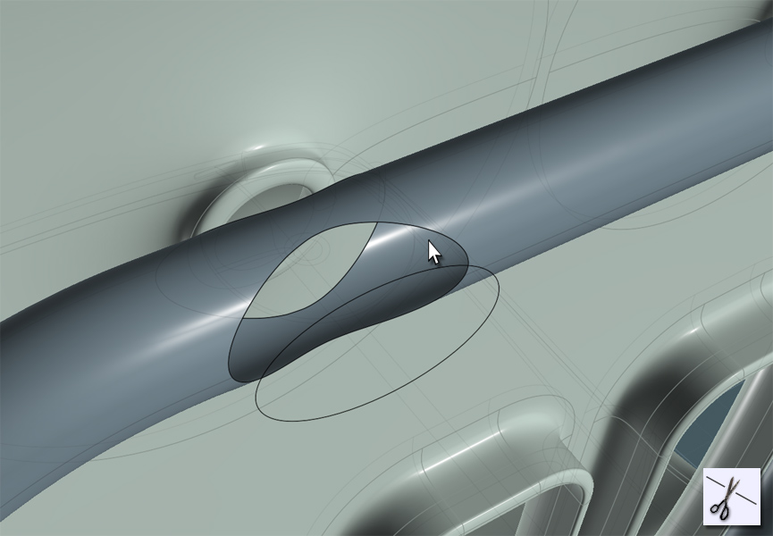
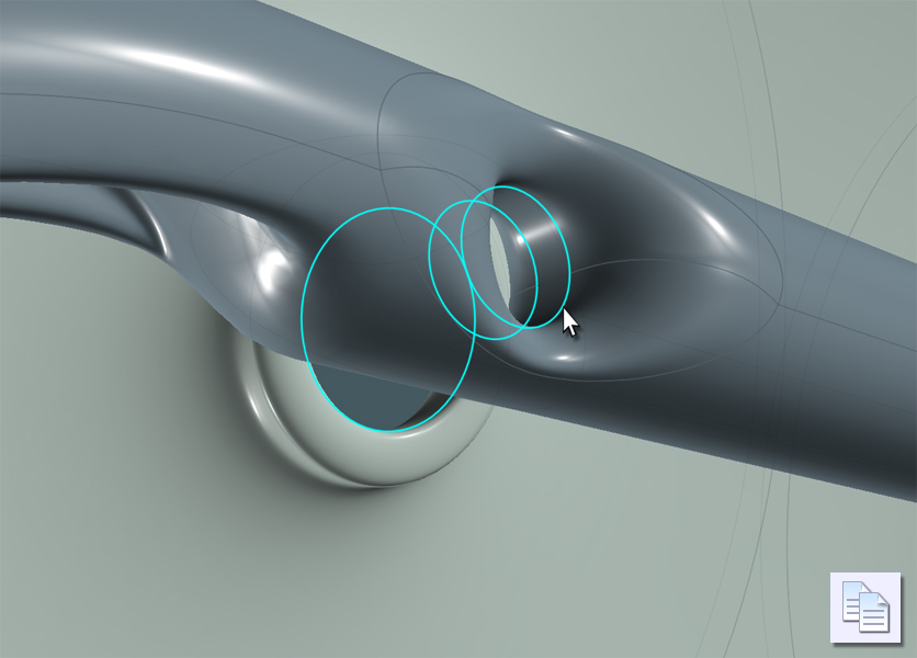
Draw an Ellipse over the holes from the back-view.


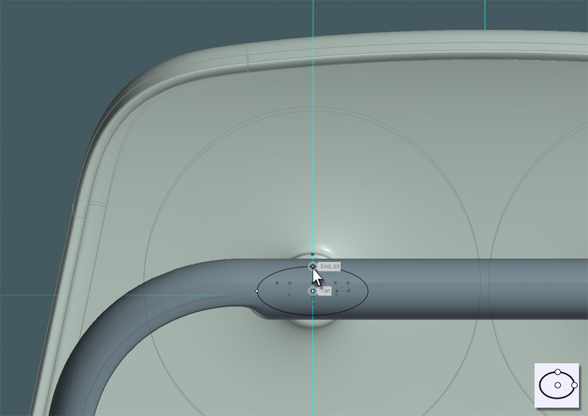
Project the Ellipse so that it creates a front and back result.


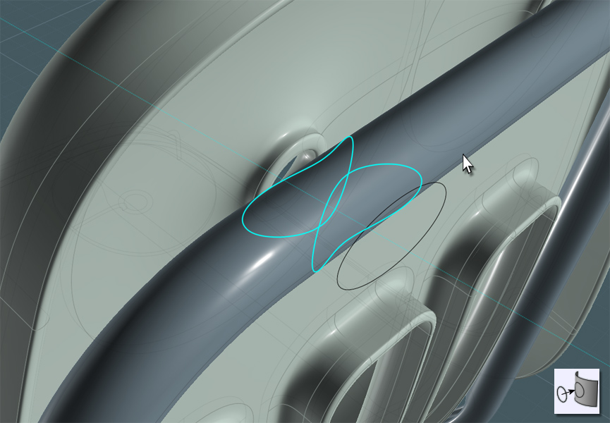
Use Trim or Boolean Difference to cut the shapes out of the tube.


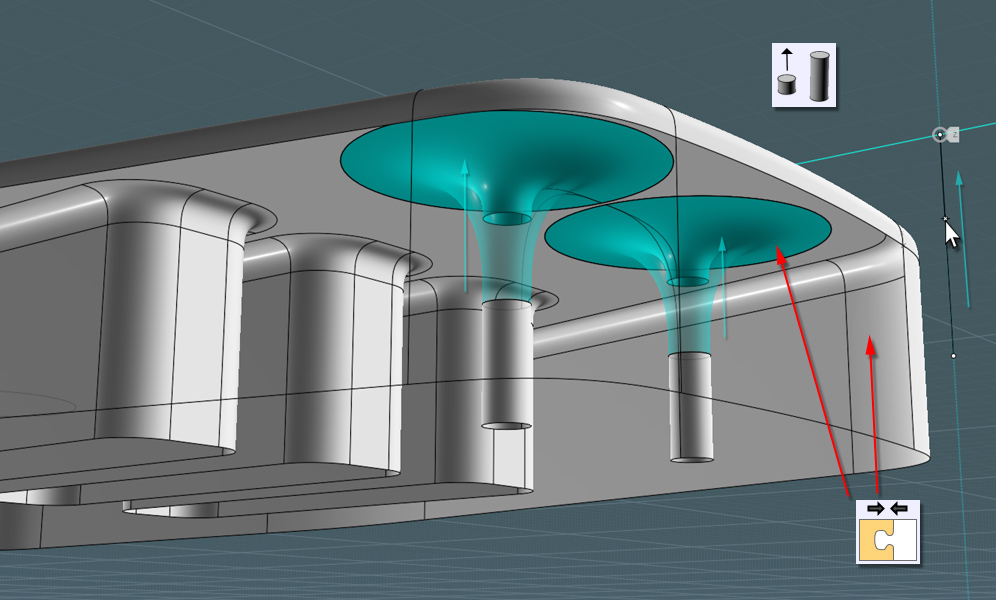
Extrude a circle to create a this inside part. A cylinder will work as well without the caps.


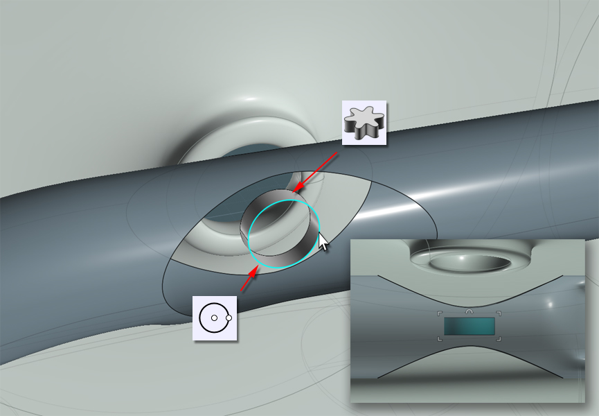
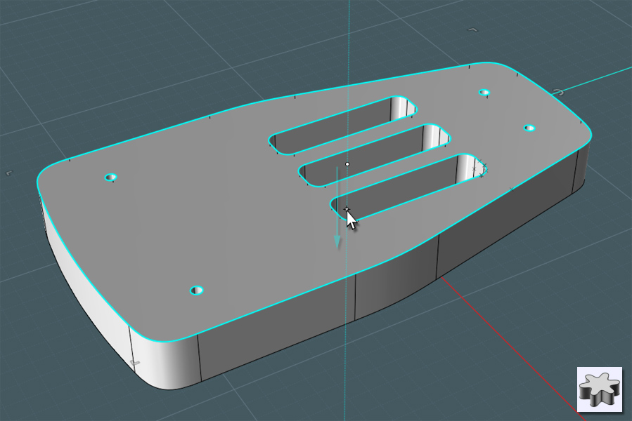
You'll notice once you 'drill-select' into the edge curves that some they may be composed of separate pieces.
Just combine them using the non-UI "Merge" command entered into the field.

Also, As you may end up with two section to match in your surfaces, go ahead and use Trim to cut the center edge curve into two corresponding halves.


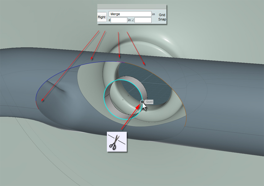
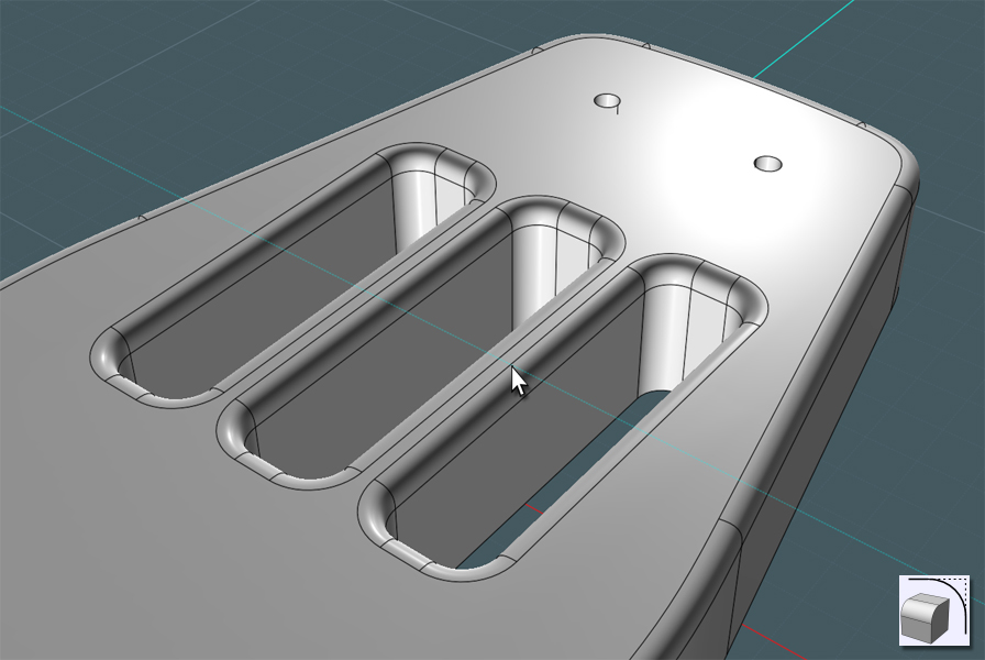
Blend these sections by selecting corresponding edge curves, then Join them all together.


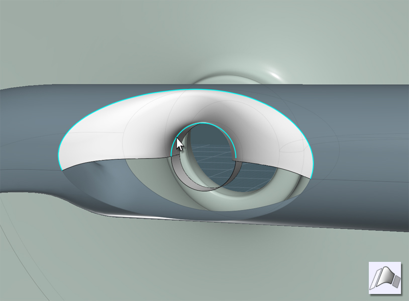
Do this for each of the four holes.


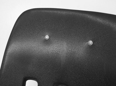
Now we need to make something that "looks" like rivets. Since this is not a mechanically-accurate model, we'll have to visually fake things.
For reference we can copy our main circles here and hide everything else.


Revolve some profiles and place them as best as you can in relation to your reference circles.
I find that it is easier to simple go to two 'ortho' views and do rotation adjustments in each one.


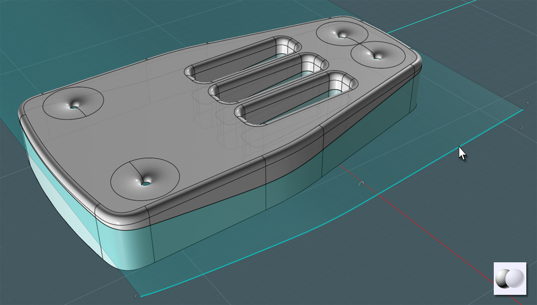
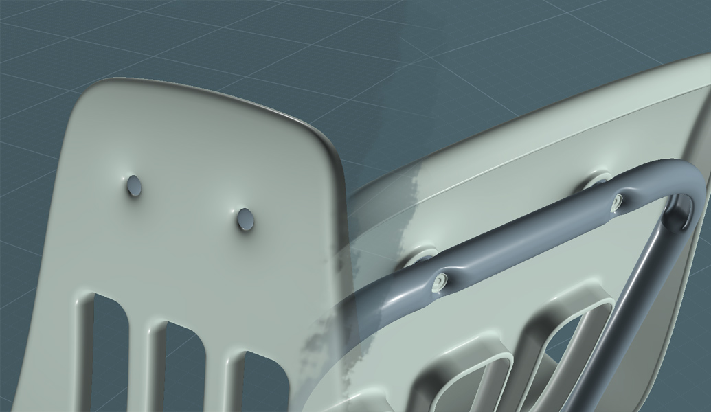
...rivets applied...


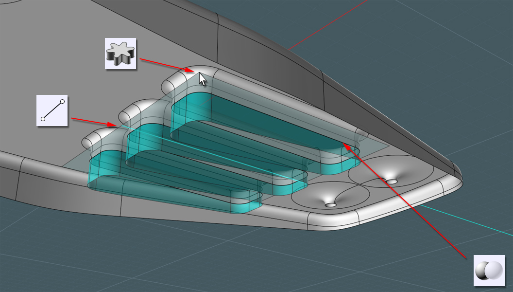
Let's build the legs. These are also rolled steel tubes.
Lets draw a few lines to be used as Sweep paths.
Note that the legs have a slight taper to the sides.


Just Fillet the corners. Keep in mind, the spacing away from the shell's lip and the frame.


Make a profile Circle for the main tube and a version that has a more flattened are which is where the tube will bend.


Since this Sweep was simpler, it gave me little issue.


Use your guides!!! Guides are a tricky thing to teach as they are so versatile and intuitive in Moi3D.
I want to use the Copy tool to make a second tube.
I wanted the second tube to follow exactly along the frame as the first. Since the frame is set at an inclined orientation,
I can't simply just copy the tube laterally.


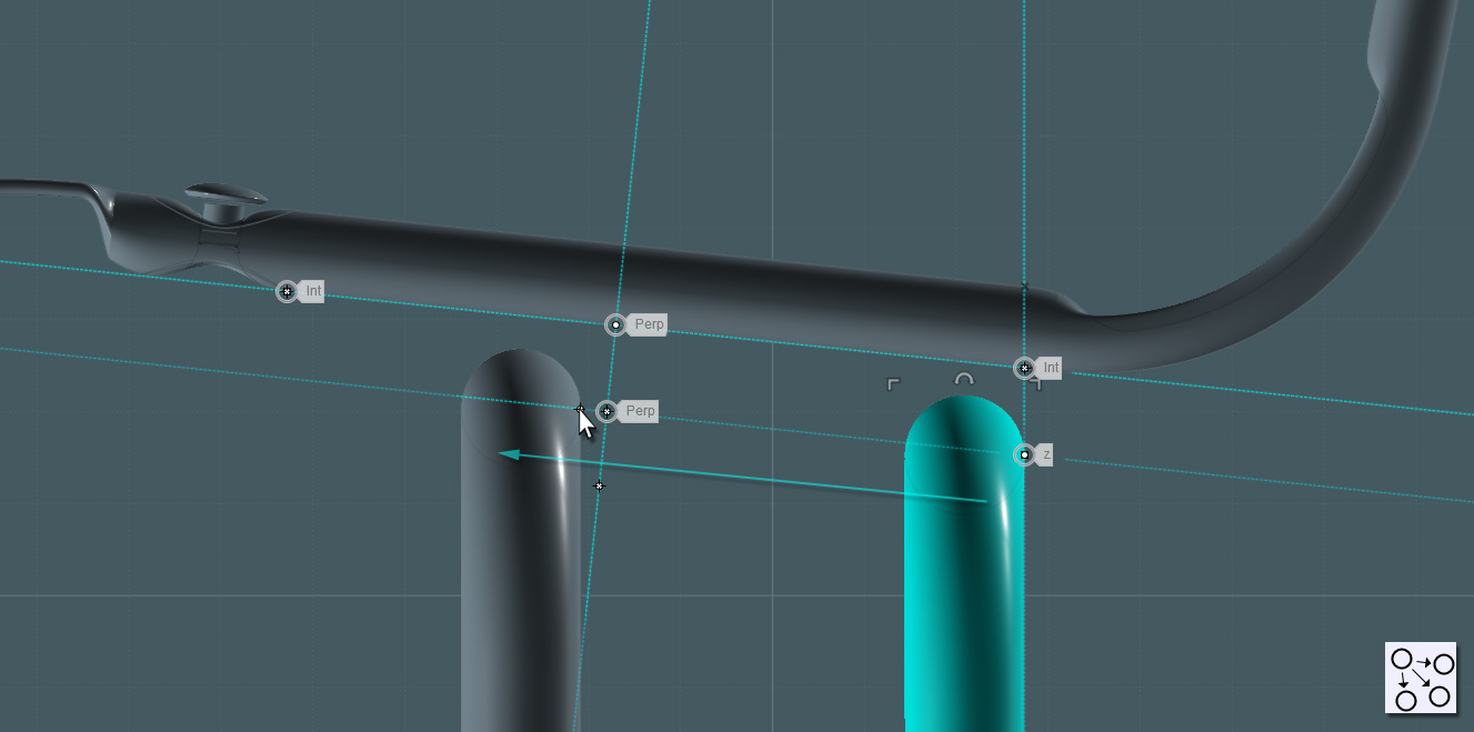
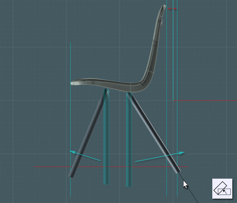
In the side-view, I'll Rotate the legs into their angled positions.
Note that the the back leg is orientated so that the feet always contact an adjacent wall before the back of the chair,
plus it offsets the center of gravity for the user.


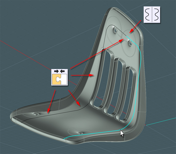
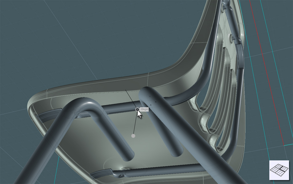
Here comes a tricky part... there needs to be a reinforcing truss to connect the legs to the frame.
This is at a strange angle so we'll need to program the C-Plane orientation in the View menu so that we're working inline with the frame.

Use the seam line on the frame part where the legs meet.


I create an interesting brace profile here by creating a poly-line and Shelling the line to add thickness.


Extrude the profile, trim other profiles and Fillet where needed to complete the shape.


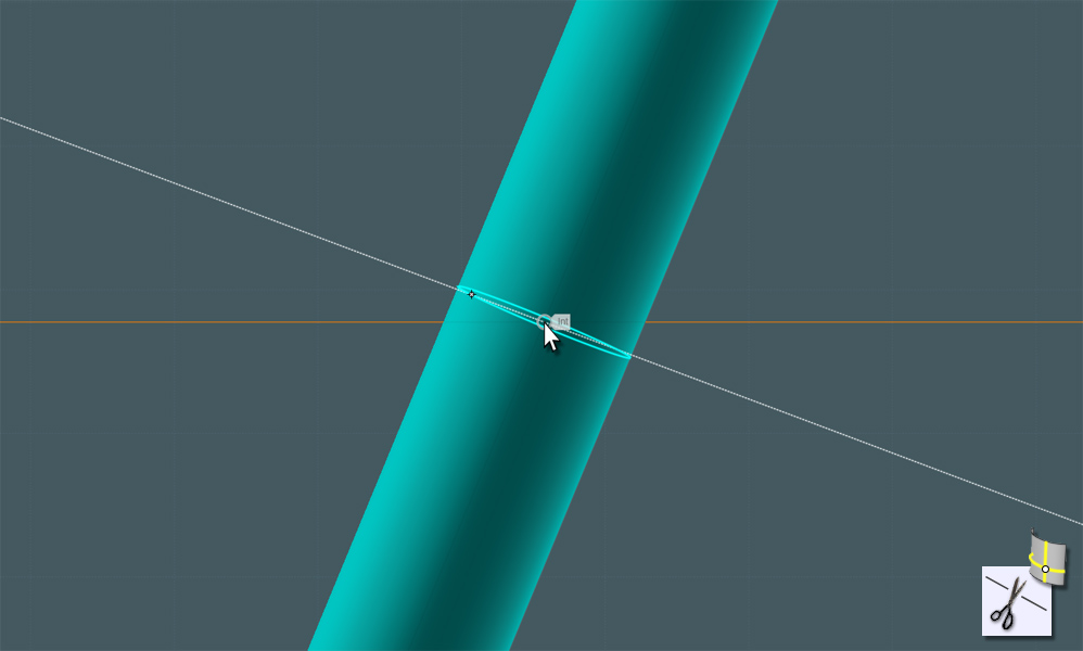
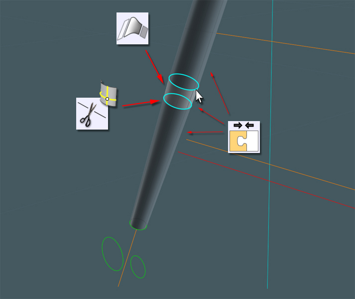
Use the new V3 Iso-Curve tool to cut the leg pipes short about halfway up.
Use Trim with Iso-Curve to save a step.
Make sure you kept the original Sweep path curve. ;-)


Make a Circle that is smaller than the one used for the legs and Orient it at the bottom where the feet will be.


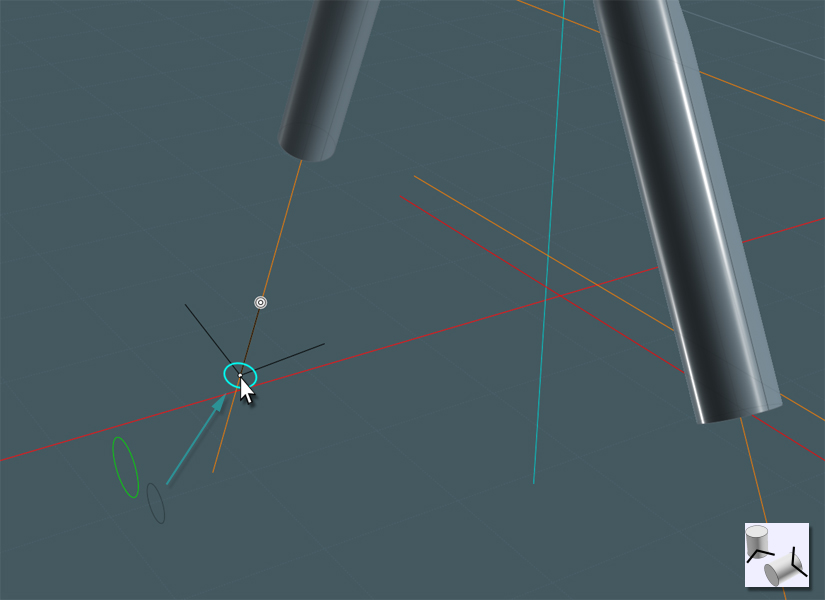
Use Loft to create a new conical shape.


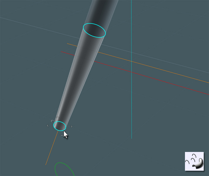
To connect the shorter leg tube with the conical tube, I used Trim with Iso-Curve to cut each shape back a little.
Then I used Blend to bring the two parts together smoothly. Just Join all parts.


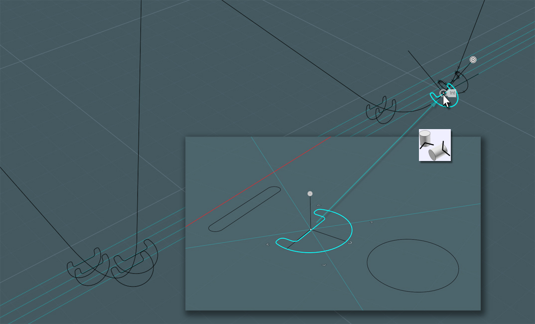
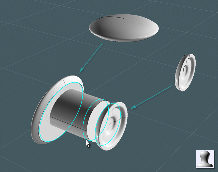
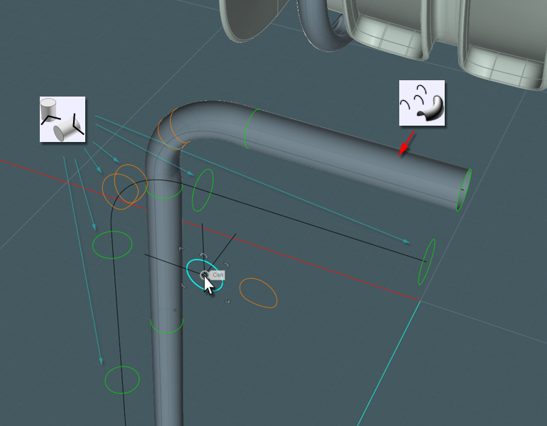
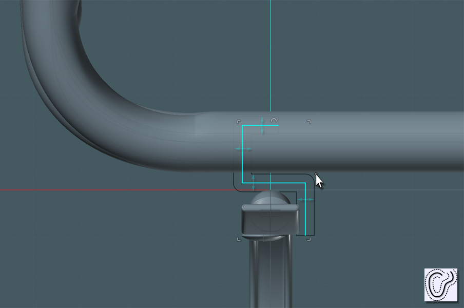
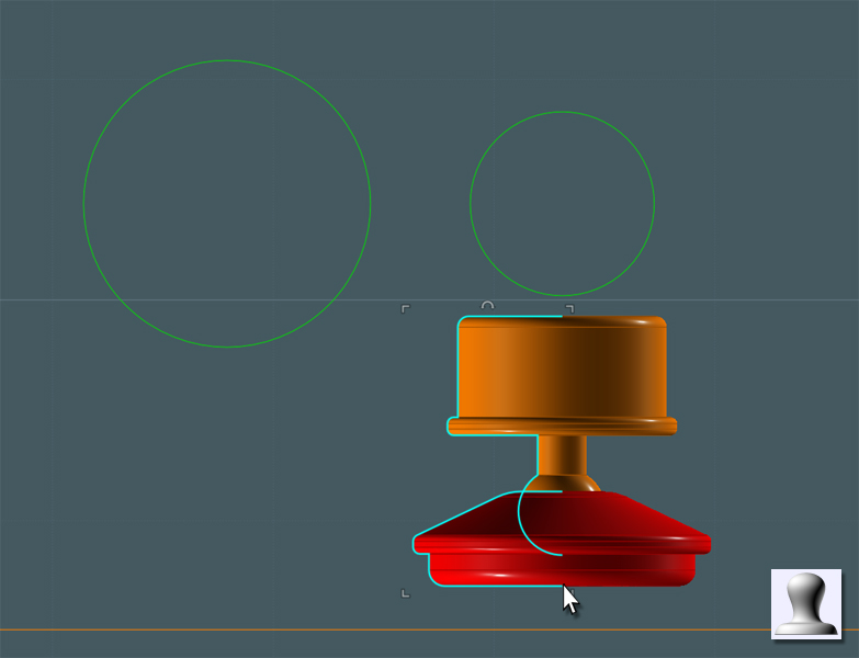
Lets make some feet castors:


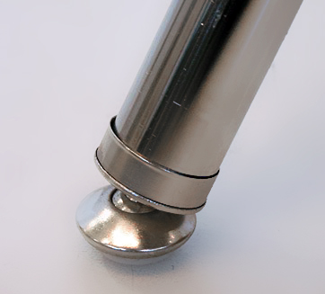
One part holes the nylon pad and the other has a ball part for swivel action... a 'ball and socket' joint.


By using the saved Sweep path curve as reference, you can use the Orient tool to place the castor.


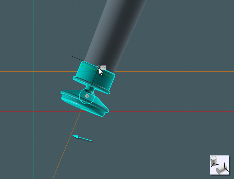
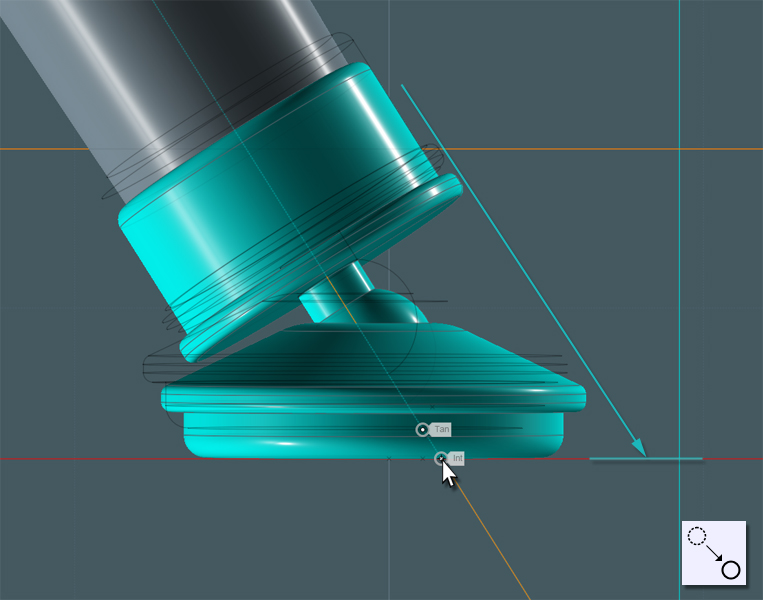
To make the castor pad flat to the floor plane, the easiest way I found was to go to two different 'ortho' views, like Right and Front,
and use Rotate to fix the angle of the objects.
There was a "Center" snap point present inside the 'ball', which is what I used to perfectly orient the part from two views.


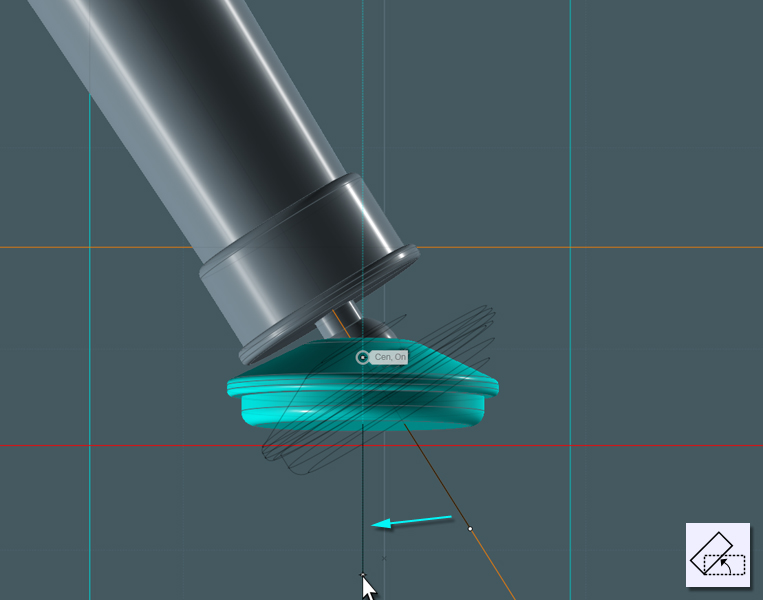
Using the Move tool, use the Sweep path to guide the part to the 'floor'.


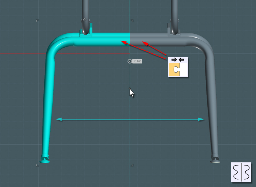
Now all you have to do is Mirror the completed legs to the other side...
Join the tubes.

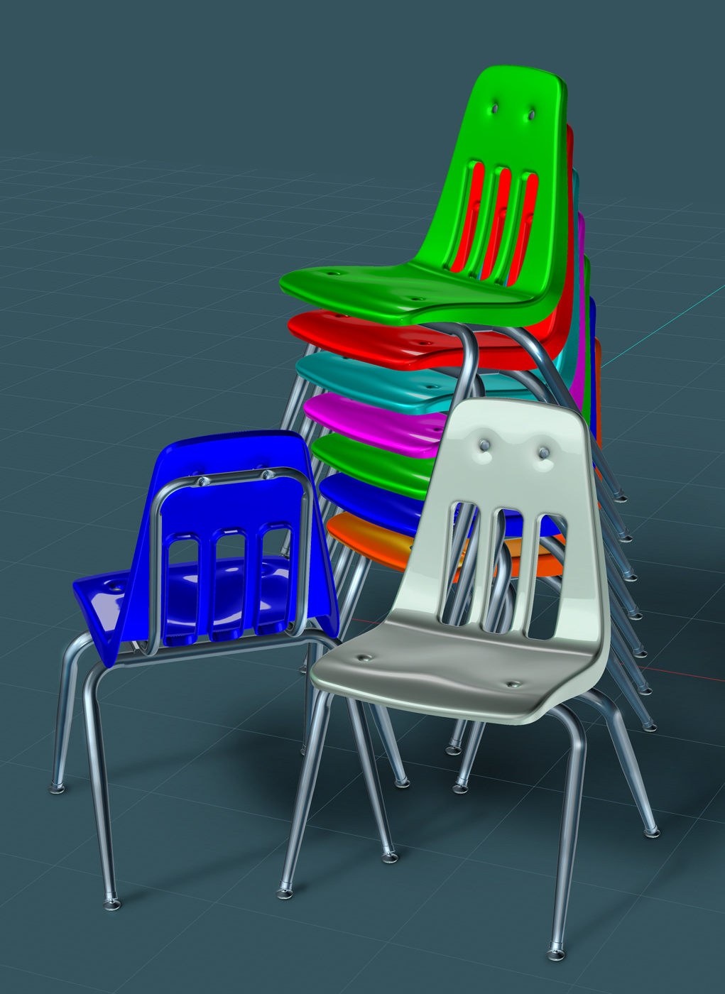
...and now you're done!


Enjoy your chair design, and send your schools to Virco for a well-designed and time-tested chair. ;-)

  Reply Reply More Options
Post Options
Reply as PM Reply as PM
Print Print
Mark as unread Mark as unread
Relationship Relationship
IP Logged

Previous
Next
 From:  Michael Gibson
5893.3 In reply to 5893.2 
Hi Mike, wow that is an awesome looking result!

Do you happen to have a file saved with the curves in it that made that sasaugey type sweep result? There is a process that tries to align profiles to reduce twist and also to flip them if needed so that doesn't happen but it looks like it's not working there. But also it may just be getting confused because you've got a quite significant change in shape in just one single step there, if you had one more sort of in-between step there instead of a sudden shift from convex to concave all in one go it could probably help it to get it right.

- Michael
  Reply Reply More Options
Post Options
Reply as PM Reply as PM
Print Print
Mark as unread Mark as unread
Relationship Relationship
IP Logged

Previous
Next
 From:  Mike K4ICY (MAJIKMIKE)
5893.4 
For those interested: Here is the link to the 3DM file for you to play around with.

http://www.mediafire.com/file/v83iha5yi0ux28k/School_Chair_Tutorial_Model.3dm

http://www.mediafire.com/file/998hfijwt1y9jfi/chair05.3dm (for some base elements)

Main Folder: https://www.mediafire.com/folder/3tlre2zc6y1qh/MoI


Please feel free to do some nice renders! ;-) I'm thinking "1980's" school room, badly maintained floor tiles and those things we used to call "black boards".
Some 'ABC' gum under the chair frame, and some scratched graffiti in the back shell plastic would be a nice touch.


Thanks Michael!

Yes, I suspect that MoI is having trouble negotiating between objects that are quite different.

I'm even having problems getting them to Loft straight when stacked.

I've tried to "flip" different profiles, Rebuild them and even Mirror them, but Sweep seems to have a mind of its own, which I why I took the more complex route.

Here is the link to the "sausage-link" file:

http://www.mediafire.com/file/t3tf6yt68ggh07s/School_Chair_Tutorial_Sweep-Issue_01.3dm

EDITED: 23 Jun 2017 by MAJIKMIKE

  Reply Reply More Options
Post Options
Reply as PM Reply as PM
Print Print
Mark as unread Mark as unread
Relationship Relationship
IP Logged

Previous
Next
 From:  Michael Gibson
5893.5 In reply to 5893.4 
Hi Mike, thanks for sending the sausage file.

In this case it's the segmented nature of those concave sections that's causing the problem, it looks like there is probably some uneven parameterization in some segments, which is not good for the seam matcher.

It's probably something that I can fix up, but an easy solution for the moment is to select all those sweep profiles and run Rebuild on them, the rebuilt curves have better parameterization and the rebuilt ones should all sweep fine.

- Michael
  Reply Reply More Options
Post Options
Reply as PM Reply as PM
Print Print
Mark as unread Mark as unread
Relationship Relationship
IP Logged

Previous
Next
 From:  BurrMan
5893.6 In reply to 5893.4 
I could only think of one addition for the render....


  Reply Reply More Options
Post Options
Reply as PM Reply as PM
Print Print
Mark as unread Mark as unread
Relationship Relationship
IP Logged

Previous
Next
 From:  Mike K4ICY (MAJIKMIKE)
5893.7 
Burr... I get your point! ;-)

Michael... My thought as well on the rebuild. I think I tried it at one point but was still dealing with the odd inverting effect.
So if everything was evened out as far as 'weighting' and 'parameterization' would the start-point position of a closed curve still effect the outcome?
  Reply Reply More Options
Post Options
Reply as PM Reply as PM
Print Print
Mark as unread Mark as unread
Relationship Relationship
IP Logged

Previous
Next
 From:  Michael Gibson
5893.8 In reply to 5893.7 
Hi Mike,

> Michael... My thought as well on the rebuild. I think I tried it at one point
> but was still dealing with the odd inverting effect.

Well, on the particular file that you sent (School_Chair_Tutorial_Sweep-Issue_01.3dm) if you do a rebuild it doesn't invert anymore...


> So if everything was evened out as far as 'weighting' and 'parameterization'
> would the start-point position of a closed curve still effect the outcome?

No, not really. That's sort of the whole point to the automatic seam matching, that it tries to get things lined up ok without you needing to have to worry about aligning all the start points yourself manually.

And actually on the messed up one it's not the start points that's really messed up, it's the direction, one is flipped where it shouldn't be.

But I'm fairly sure it's because the connection lines that are used for twist minimization are not getting dispersed very evenly across the segmented curve, that's what the uneven parameterization can cause.

- Michael
  Reply Reply More Options
Post Options
Reply as PM Reply as PM
Print Print
Mark as unread Mark as unread
Relationship Relationship
IP Logged

Previous
Next
 From:  Mike K4ICY (MAJIKMIKE)
5893.9 In reply to 5893.8 
Aha! That worked Michael, thanks!

And easier still, I was able to rebuild all the profiles in place in one Rebuild operation.

Well if tutorials are good for one thing, it's education. ;-)
  Reply Reply More Options
Post Options
Reply as PM Reply as PM
Print Print
Mark as unread Mark as unread
Relationship Relationship
IP Logged

Previous
Next
 From:  Michael Gibson
5893.10 In reply to 5893.9 
Hi Mike, I'm looking into doing some changes in the seam matcher thingy to test samples separated by arc length (by distance traveled along the curve) instead of by traveling in parameter space, that should hopefully make the original case work without any rebuild. The only tricky part is that traveling by arc length along a curve requires more computation, it's not as simple as traveling by parameter values.

- Michael
  Reply Reply More Options
Post Options
Reply as PM Reply as PM
Print Print
Mark as unread Mark as unread
Relationship Relationship
IP Logged

Previous
Next
 From:  Frenchy Pilou (PILOU)
5893.11 
Ah a very cool precise one!

French translation will be made the next month in June ;)
---
Pilou
Is beautiful that please without concept!
My Gallery
  Reply Reply More Options
Post Options
Reply as PM Reply as PM
Print Print
Mark as unread Mark as unread
Relationship Relationship
IP Logged

Previous
Next
 From:  TpwUK
5893.12 In reply to 5893.2 
Good job Mike. I love to see your workflow and technique - so clean and pure. Sure you get the odd glitch, but your style is just so darn good!

Martin Spencer-Ford
  Reply Reply More Options
Post Options
Reply as PM Reply as PM
Print Print
Mark as unread Mark as unread
Relationship Relationship
IP Logged

Previous
Next
 From:  Mike K4ICY (MAJIKMIKE)
5893.13 In reply to 5893.10 
Michael... Thanks. I'll be sure to test-drive the enhancement. If it's like the "Uniform" mode in Network (which I use a lot), it may yield some nice results.

Pilou... Très bon. Comme le fromage parfait et le vin, il doit prendre le temps. Je suis très reconnaissant pour votre contribution. ;-)


Martin... Thanks for the compliment! MoI just simply lends itself to a good pleasant workflow.

I hope the step-by-step snapshots teach well enough.
  Reply Reply More Options
Post Options
Reply as PM Reply as PM
Print Print
Mark as unread Mark as unread
Relationship Relationship
IP Logged

Previous
Next
 From:  mcramblet
5893.14 
Mike-

Is it ok to say in this forum that I love you and hate you at the same time? I love your tutorials, I use them (and your website) frequently as reference. I kind of hate you (ok, not really) because you make things look so simple and easy. You are, indeed, one of those that I'd consider a MoI Jedi. Thank-you for taking the time to put these tutorials together and for sharing them with the forum. I know that I benefit greatly from them.

Michael Cramblet
Packaging Design
Phone: 616-574-6271
 
  Reply Reply More Options
Post Options
Reply as PM Reply as PM
Print Print
Mark as unread Mark as unread
Relationship Relationship
IP Logged

Previous
Next
 From:  Mike K4ICY (MAJIKMIKE)
5893.15 In reply to 5893.14 
Michael C...

Thank you for your really great compliment! That really brightened my day. :-)

I'm really glad that, especially you, as well as others value the techniques I have to show.
I'm just a tee-shirt artist by day, but don't you get to work with really cool packaging design?

There's a part of me that enjoys sharing instructional knowledge with others.
They call me an "Elmer" in the ham radio circles.

Michael G. has done such a great job at developing MoI to be so bluntly simple to use and intuitive that I feel that anyone with a little training can realize their hidden CAD talents.
Notice how all I have to do is show one of the few icon symbols and the rest speaks for itself?
  Reply Reply More Options
Post Options
Reply as PM Reply as PM
Print Print
Mark as unread Mark as unread
Relationship Relationship
IP Logged

Previous
Next
 From:  ed (EDDYF)
5893.16 
Dang Mike - your tutorials get better each time. You definitely earned your black belt in MoI.

That chair brings back memories. Especially the times I had to sit in it facing the corner in 4th grade.

Ed
  Reply Reply More Options
Post Options
Reply as PM Reply as PM
Print Print
Mark as unread Mark as unread
Relationship Relationship
IP Logged

Previous
Next
 From:  Samuel Zeller
5893.17 
Wow really great modeling and tutorial !

I learned new things :)

Thanks !
--
shapenoid.com stojan-voumard.com
  Reply Reply More Options
Post Options
Reply as PM Reply as PM
Print Print
Mark as unread Mark as unread
Relationship Relationship
IP Logged

Previous
Next
 From:  ed (EDDYF)
5893.18 
Here ya go Mike. Your chairs modeled in KeyShot against a meeting room HDR.

Click image to view full size.

Ed

EDITED: 17 May 2013 by EDDYF

Image Attachments:
Size: 635.3 KB, Downloaded: 731 times, Dimensions: 753x705px
  Reply Reply More Options
Post Options
Reply as PM Reply as PM
Print Print
Mark as unread Mark as unread
Relationship Relationship
IP Logged

Previous
Next
 From:  Mike K4ICY (MAJIKMIKE)
5893.19 
Ed, thank you!!! They're so realistic, it's spooky.

Even the colors.... ahh the memories... no... no... flashbacks!.... awful flashbacks!
  Reply Reply More Options
Post Options
Reply as PM Reply as PM
Print Print
Mark as unread Mark as unread
Relationship Relationship
IP Logged

Previous
Next
 From:  ed (EDDYF)
5893.20 In reply to 5893.19 
Thanks Mike. I had my share of "ass time" in those chairs too.

Yeah - KeyShot now has a color picker eye-drop tool built into their material editor. Just open the website for the chair mfg., pop open their color selection options, take a sample - done.

KeyShot also now has Mold-Tech plastic textures, so I picked one based on memory.

I think my camera focal length doesn't quite match the background, but it's just a quick and dirty render. It sure helps to have a realistic model to work with!

Ed
  Reply Reply More Options
Post Options
Reply as PM Reply as PM
Print Print
Mark as unread Mark as unread
Relationship Relationship
IP Logged
 

Reply to All Reply to All


Show messages:  1-20  21-40  41-43