How make that ?
 1-20  21-40  41-60  61-75

Previous
Next
 From:  amur (STEFAN)
5590.61 
Hi all,

i find this thread very interesting and thought how about using a poly model created in MoI, then beveled in modo and finally bought into T-Splines demo for Rhino. Here are the results:


Regards
Stefan

EDITED: 4 Nov 2016 by STEFAN

  Reply Reply More Options
Post Options
Reply as PM Reply as PM
Print Print
Mark as unread Mark as unread
Relationship Relationship
IP Logged

Previous
Next
 From:  blowlamp
5590.62 
Do other apps and kernels provide for a multi-radius blend like in this pic?


Martin (2).
Attachments:

Image Attachments:
Size: 103.7 KB, Downloaded: 30 times, Dimensions: 1397x774px
  Reply Reply More Options
Post Options
Reply as PM Reply as PM
Print Print
Mark as unread Mark as unread
Relationship Relationship
IP Logged

Previous
Next
 From:  Luis (LGRIJALVA)
5590.63 In reply to 5590.59 
Here is the result using cover surface tool on sharfx to make a cover on the hole (I think viacad also have this one), first attempt don't go fine, until i select "export selected only" and "end line as pc" options on export dialog. This way the solid goes flawlessly into Moi, also, sat was exported as v4.0
here is the resulting file


Luis G

EDITED: 11 Dec 2012 by LGRIJALVA


  Reply Reply More Options
Post Options
Reply as PM Reply as PM
Print Print
Mark as unread Mark as unread
Relationship Relationship
IP Logged

Previous
Next
 From:  Mike K4ICY (MAJIKMIKE)
5590.64 
Michael, this pic here is a standard G2 fillet done in MoI... it isn't all that bad for a "Star" patch.

Was this done with the 'star' patch routine or was it some special analytical case just for fillets?


I would take the 'lumpy' resultant 'star' mechanism over an empty hole any day!

And perhaps including it could be a stop-gap until a better system is implemented, kinda like how you improved the Network later.
Since the 'star' patch is in the system already, maybe just a non-UI text command would suffice.

But none the less, I want not to sound pushy, I really do appreciate you're open collaboration with us all.

:-)
  Reply Reply More Options
Post Options
Reply as PM Reply as PM
Print Print
Mark as unread Mark as unread
Relationship Relationship
IP Logged

Previous
Next
 From:  BurrMan
5590.65 In reply to 5590.59 
Hey Blowlamp,

""""""""""""The result is in the picture which to my eyes looks a mess and surely not what I would expect ACIS to produce. """""""""""

That happened to me if I tried to "move" a control point after the points were on. The model wouldnt undo from it. It could be display driver related.
  Reply Reply More Options
Post Options
Reply as PM Reply as PM
Print Print
Mark as unread Mark as unread
Relationship Relationship
IP Logged

Previous
Next
 From:  blowlamp
5590.66 In reply to 5590.63 
Hi Luis.

Good to see you here from the ViaCAD/Shark forum!

Sorry though, but I can't get any of that to work for me - any chance of a bit more detail please?


Martin (2).
  Reply Reply More Options
Post Options
Reply as PM Reply as PM
Print Print
Mark as unread Mark as unread
Relationship Relationship
IP Logged

Previous
Next
 From:  blowlamp
5590.67 In reply to 5590.65 
Hi Burr.

That picture is the result of un-trimming the n-patch after first converting the solid to surfaces. I also included the file of the patch for anyone interested to look at.


Martin (2).
  Reply Reply More Options
Post Options
Reply as PM Reply as PM
Print Print
Mark as unread Mark as unread
Relationship Relationship
IP Logged

Previous
Next
 From:  Michael Gibson
5590.68 In reply to 5590.60 
Hi OSTexo, thanks for posting that VSR blend - that's one of the best star type blends that I've seen. There is no hint of lumpiness between adjacent left-right neighbors of the filling surface, so it doesn't have the kind of residual star pattern artifact that seems to be usually present in this kind of blend.

The main quality problem that I see with it is that it has a somewhat flat-ish shape through most of it and it kind of has a bit of a sudden bend in it right when it comes to the outer boundary. This is interesting since with other star blend mechanisms it's this area that is actually well shaped.

Also the surfaces generated by VSR are very light - they are higher degree (degree 5) single span surfaces instead of cubics. This is a fairly different kind of structure than the regular star blend mechanism which is usually based off of making degree 3 Coons patches for each surface. I think that VSR is kind of specialized in its focus on working with single-span surfaces, undoubtedly some general techniques coming from ICEM Surf coming into play there.

It's not exactly perfect but I think it does show that the star blend mechanism is not necessarily 100% fatally flawed.

Using only single span surfaces would probably have some downsides in other situations though, like if you were trying to fill in a hole where the edges were sort of wiggly and not so uniformly shaped a single span surface would probably not match up very well then...

- Michael
  Reply Reply More Options
Post Options
Reply as PM Reply as PM
Print Print
Mark as unread Mark as unread
Relationship Relationship
IP Logged

Previous
Next
 From:  Michael Gibson
5590.69 In reply to 5590.61 
Hi Stefan, the t-spline result is very interesting! The interior region of each area seems to be nice but it kind of looks a bit odd at the borders between every shape, I think there may be some fairly tight little bends in the shapes where pieces meet up.

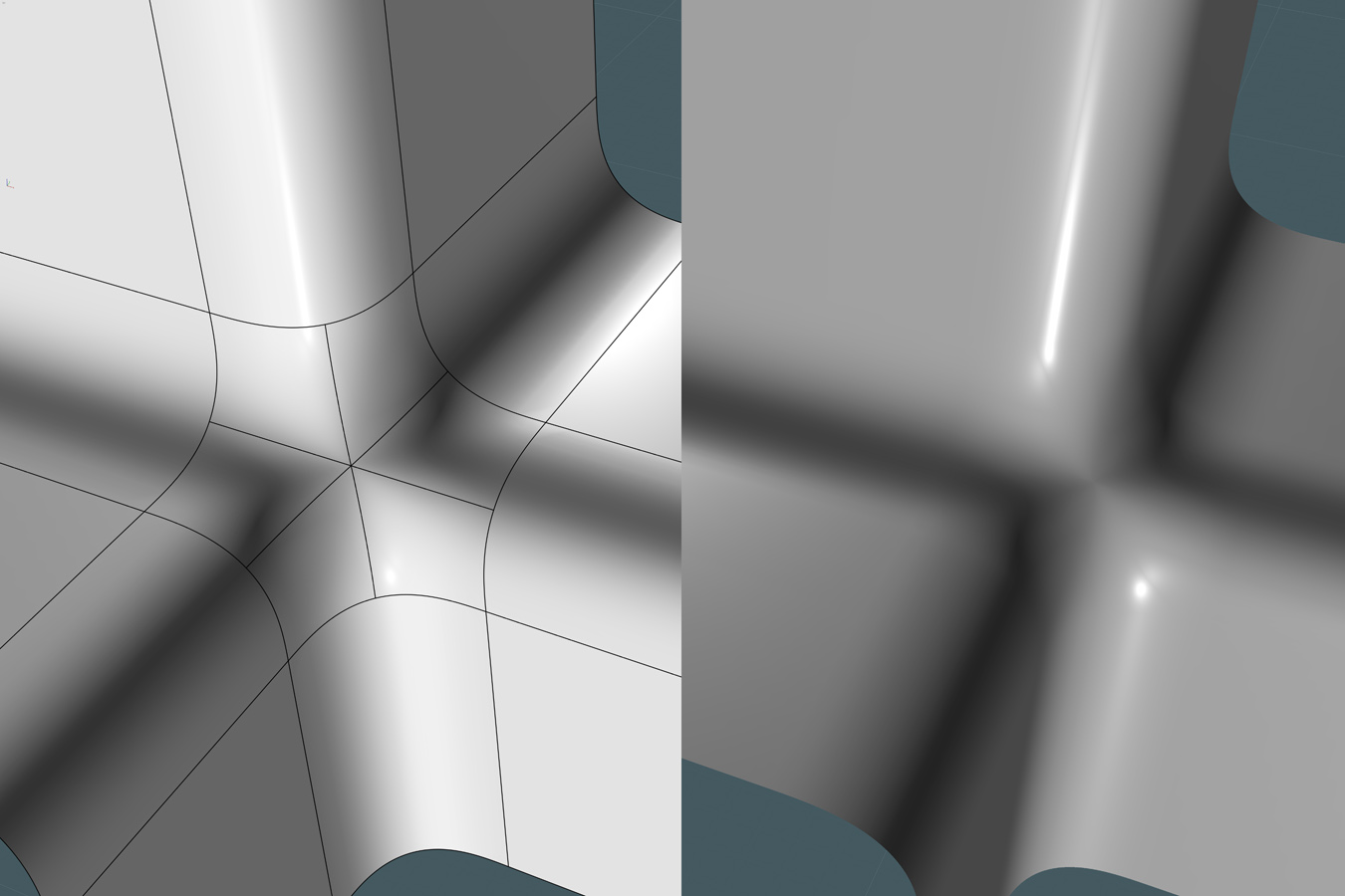
Notice here how dark the "fillet" surfaces are right where they meet up with the planar area:


I think there is some kind of little small sized lump or tiny dip in those areas, it kind of makes the juncture between all the cylinder shaped fillets and the adjacent planes to be kind of more accented then they normally are, that's kind of what catches my eye as being slightly weird looking with this example.

I also extracted some of the edges of those surfaces and examined them in Rhino using a curvature graph and yeah you can see that there is a sudden spike in curvature right at that plane/fillet juncture area, so there does seem to be some irregularity in shape in these plane/cylinder juncture areas when using this technique, you kind of basically lose the accuracy of planes and cylinders with things all glommed together into big surfaces like this. Here's the curvature graph of one of those surface edges:


A normal cylinder/plane juncture would not have that sudden spike in curvature where they connect together, there would normally be no curvature for the planar part, and then only a constant circle curvature for the cylinder part, this has a kind of little dip or bump where the 2 shapes (planar and cylindrical) come together.

So it kind of opens a bag of worms of problems in the plane/cylinder areas where the regular NURBS objects are well behaved...

- Michael

  Reply Reply More Options
Post Options
Reply as PM Reply as PM
Print Print
Mark as unread Mark as unread
Relationship Relationship
IP Logged

Previous
Next
 From:  Michael Gibson
5590.70 In reply to 5590.65 
Hi Burr,

> That happened to me if I tried to "move" a control point after the points were on. The model
> wouldnt undo from it. It could be display driver related.

That happened to me too, I think it's just a bug in undo in ViaCAD, probably not driver related.

- Michael
  Reply Reply More Options
Post Options
Reply as PM Reply as PM
Print Print
Mark as unread Mark as unread
Relationship Relationship
IP Logged

Previous
Next
 From:  Michael Gibson
5590.71 In reply to 5590.62 
Hi Martin,

> Do other apps and kernels provide for a multi-radius blend like in this pic?

You mean with 2 different radius values coming together at a single juncture? Yes, a lot of CAD programs do allow for that, and I believe it's even supported in the geometry library that MoI uses, I have a general plan to make that possible in the future by some method in Fillet, probably something like some button where you could say "new fillet set" and then pick a new sequence of edges to fillet with a different radius value without leaving the fillet command.

- Michael
  Reply Reply More Options
Post Options
Reply as PM Reply as PM
Print Print
Mark as unread Mark as unread
Relationship Relationship
IP Logged

Previous
Next
 From:  Michael Gibson
5590.72 In reply to 5590.64 
Hi Mike,

> Was this done with the 'star' patch routine or was it some special analytical case just for fillets?

It's a general star-patch hole filling routine that is calculating that in MoI.

And yeah it's not exactly horrible but if you generate a heavier tessellation of the model you'll see a kind of star pattern of ridges radiating out from the center point. Often times the ridges can be fairly pronounced especially when the boundary is not quite so uniformly shaped as in these fillet cases.

- Michael
  Reply Reply More Options
Post Options
Reply as PM Reply as PM
Print Print
Mark as unread Mark as unread
Relationship Relationship
IP Logged

Previous
Next
 From:  OSTexo
5590.73 
Hello,

Aside from the control point modeling it looks like the shape factor slider can control how that actually looks. I believe you're right about the ICEM connection, I think at least one person over there at VSR had some heavy involvement in that product.

Attachments:

  Reply Reply More Options
Post Options
Reply as PM Reply as PM
Print Print
Mark as unread Mark as unread
Relationship Relationship
IP Logged

Previous
Next
 From:  Michael Gibson
5590.74 In reply to 5590.63 
Hi Luis,

> Here is the result using cover surface tool on sharfx to make a cover on the hole (I think viacad also have this one)

This one I think is definitely better than the previous one that came straight from filleting - this one is both lighter in control point count and also "stiffer" with less lumpiness to it.

That's very interesting that it's fairly different from the one that comes from filleting. I wonder if it's actually using a different mechanism for generating the surface or whether it's just a different set of parameters for the surface generation...

It instead though has a different problem where it's noticeably not G1 to much of the boundary areas though, note the sharp creases in these areas:


- Michael
Attachments:

  Reply Reply More Options
Post Options
Reply as PM Reply as PM
Print Print
Mark as unread Mark as unread
Relationship Relationship
IP Logged

Previous
 From:  Luis (LGRIJALVA)
5590.75 In reply to 5590.66 
Hello Martin, thanks, glad to see you here too, seems that we are same kind of people on the same quest: Hunting of good 3d software :)

Regarding this topic, I don get the way to do this patch on Moi, so, back to via cad/shark, I do a few more tests and seems that the key is to use the rebuild surface tool on the patch blend surface, this way, moi imports Sat, Step and IGS format without problem


Michael:
Notice that my first attempt I use the 3dm model downloaded from this forum that doesn't have the patch, and I patch the hole using the cover surface tool, so, maybe an internal rebuild occur on the process and that is the difference with previous ones,

Martin: In this ones I make a model using the blend tool with setback at 80 (working with mm), then rebuild the surface in question, here both files, the sat resulted from exporting and Moi file with the imported file:

  Reply Reply More Options
Post Options
Reply as PM Reply as PM
Print Print
Mark as unread Mark as unread
Relationship Relationship
IP Logged
 

Reply to All Reply to All


Show messages:  1-20  21-40  41-60  61-75