How make that ?
 1-20  21-40  41-60  61-75

Next
 From:  Frenchy Pilou (PILOU)
5590.1 
How make this yellow corner with Moi ?


My try :)
Some arcs circles, Network or sweep on the borders, and sweep on the center


File 3DM of the first image made with Shark by GuillaumeG
http://moi3d.com/forum/get_attachment.php?webtag=MOI_FRANCAIS&hash=224e4dfdc626fa6869f10c039e55a456&filename=valise.3dm

EDITED: 7 Dec 2012 by PILOU

  Reply Reply More Options
Post Options
Reply as PM Reply as PM
Print Print
Mark as unread Mark as unread
Relationship Relationship
IP Logged

Previous
Next
 From:  Michael Gibson
5590.2 In reply to 5590.1 
Hi Pilou, there is not currently any very good method to make a result like that directly in MoI - using Shark or Rhino to do it and then importing the result into MoI would be what I would recommend currently.

That's often times called an N-sided patch, and it's an area that the people who make the geometry library that MoI uses are actively working on right now, so I hope to add that functionality in to MoI but it's not in there yet.

If you were to extract that surface all by itself and turn on its control points you would see that the actual surface extends larger than the area that you see there, it's a bigger surface that is fit to pass through those curves which then has trims applied to it to cut the outer area away.

If you were to try to construct it manually in MoI without using any n-sided patch command, you would probably try to do a similar thing of building an initially bigger surface that would then get trimmed. That can be tricky though.

- Michael
  Reply Reply More Options
Post Options
Reply as PM Reply as PM
Print Print
Mark as unread Mark as unread
Relationship Relationship
IP Logged

Previous
Next
 From:  TpwUK
5590.3 In reply to 5590.1 
I honestly thought it was just an extruded square with rounded corners set to produce a capsule shape - Like a tablet, which had then had trims or booleans applied to give it back some planar surfaces to the ends and sides

Not tried it as I am getting ready to get the mrs to the hospital

Martin Spencer-Ford
  Reply Reply More Options
Post Options
Reply as PM Reply as PM
Print Print
Mark as unread Mark as unread
Relationship Relationship
IP Logged

Previous
Next
 From:  blowlamp
5590.4 
I'm not good enough with MoI yet to emulate that effect, but within the ViaCAD Blend tool (Fillet tool in MoI), there is a Setback option that seems to give a similar result to Frenchy's example shot.

Is this available in MoI's geometry library?

Here's a sample file with several blocks to show the effect - the one closest to the origin has no Setback applied.


Martin.
Attachments:

  Reply Reply More Options
Post Options
Reply as PM Reply as PM
Print Print
Mark as unread Mark as unread
Relationship Relationship
IP Logged

Previous
Next
 From:  Michael Gibson
5590.5 In reply to 5590.4 
Hi Martin,

> Is this available in MoI's geometry library?

It is actually, although without an n-sided blend working it produces a multi-surface blend instead.

This is one of those things where it's hard to decide whether to add the complexity in to the command for an extra option - every option added increases complexity and slips a little bit of the streamlined nature of MoI away...

- Michael
  Reply Reply More Options
Post Options
Reply as PM Reply as PM
Print Print
Mark as unread Mark as unread
Relationship Relationship
IP Logged

Previous
Next
 From:  Mike K4ICY (MAJIKMIKE)
5590.6 
Is it just me or does anyone else notice that the edges of that corner surface has a minute aberrations, or a 'rumply' appearance?

I always thought it would seem like a viable solution to use multiple three or four-sided surfaces matched together to provide the solution to such a complex area.

Wouldn't forcing the sides and corners of a surface to be stretched like some leather skin or screen mesh would yield inaccuracies.

I could be wrong, but to me it seems logical to use two three-sided surfaces matched together at some median seam to get a patch that would meet at six-sides like in this example.

  Reply Reply More Options
Post Options
Reply as PM Reply as PM
Print Print
Mark as unread Mark as unread
Relationship Relationship
IP Logged

Previous
Next
 From:  Michael T. (MICTU_UTCIM)
5590.7 
Hi blowlamp, there is also vertex blend in ViaCAD for corner radii.

Michael T.
Michael Tuttle a.k.a. mictu http://www.coroflot.com/DesignsByTuttle
  Reply Reply More Options
Post Options
Reply as PM Reply as PM
Print Print
Mark as unread Mark as unread
Relationship Relationship
IP Logged

Previous
Next
 From:  blowlamp
5590.8 In reply to 5590.5 
Michael.


> It is actually, although without an n-sided blend working it produces a multi-surface blend instead.

Interesting that it's already in there, but sorry, I'm not knowledgeable enough about CAD to understand what that really means. :)


Just my general thoughts about the added complexity conundrum.

As a user, I'm finding MoI to be very well considered in its toolset and ease of use, but personally, I'd be more that willing to accept a little overhead to allow the exposure of powerful extensions to the toolset.

That MoI isn't overloaded with a multiplicity of tools is a key plus point for me.
However, a rich choice of options from within a particular tool is not something I find to be a problem, as MoI will have already guided me to the right place, leaving me with only one or two more steps to complete.

In v3, you've expanded the Extrude tool and it now has probably one of the 'busiest' dialogue areas, but everything still works like a treat and it's added another dimension to this tool's function, so in my opinion MoI is all the better for having extras such as these.

If it could eventually be implemented, I think that in situations like Frenchy's example, Setback could be a simple to use complement to the Fillet tool - and it's almost mandatory for making good dice. :)


Martin (2).
  Reply Reply More Options
Post Options
Reply as PM Reply as PM
Print Print
Mark as unread Mark as unread
Relationship Relationship
IP Logged

Previous
Next
 From:  blowlamp
5590.9 
Mike.

No, it's not only you that can see the wrinkles :)


Michael T.

Yes, very good for knocking off the corners of machine tool components etc.


Martin.

EDITED: 7 Dec 2012 by BLOWLAMP

Image Attachments:
Size: 386.2 KB, Downloaded: 32 times, Dimensions: 826x769px
  Reply Reply More Options
Post Options
Reply as PM Reply as PM
Print Print
Mark as unread Mark as unread
Relationship Relationship
IP Logged

Previous
Next
 From:  Michael Gibson
5590.10 In reply to 5590.6 
Hi Mike,

> Is it just me or does anyone else notice that the edges of that corner surface
> has a minute aberrations, or a 'rumply' appearance?

These kinds of flaws can happen pretty easily with n-sided patch mechanisms. It's pretty tricky to make a really good implementation that forces the surface close enough through the curves but also does not make ripples in the surface in other spots where there are not any fitting points.


> I always thought it would seem like a viable solution to use multiple three or four-sided
> surfaces matched together to provide the solution to such a complex area.

MoI's geometry library does currently use this method - the problem then shifts to there having a tendency to have noticeable ridges and waves in the side-to-side connections, making a kind of star-like pattern that you can see on the generated surfaces.


> Wouldn't forcing the sides and corners of a surface to be stretched like some
> leather skin or screen mesh would yield inaccuracies.

It does - but if it's not accurate enough a good patch fitting mechanism would then add more points to the surface being stretched so that it could be manipulated in finer amounts until it adhered closely enough to the boundary curves.

The good thing about the star method is that it is able to adhere directly to the boundary curves meeting them exactly. But I've done a fair amount of research on the star method trying to refine it and I have not been able to find any way to reduce the star patterns that result. Basically the problem is that at the center vertex point each surface only tries to adapt its shape to be smooth to its immediate left-right neighbors and this tends to produce a ridge (a smooth one but a ridge none the less).

It's actually a good example of how having surface continuity is not a panacea for surface quality...

- Michael
  Reply Reply More Options
Post Options
Reply as PM Reply as PM
Print Print
Mark as unread Mark as unread
Relationship Relationship
IP Logged

Previous
Next
 From:  Michael Gibson
5590.11 In reply to 5590.8 
Hi Martin,

> and it's almost mandatory for making good dice. :)

That's sort of the problem - its use only seems to come up very rarely...

Just in general I'm not crazy about adding in options that only have any use in very rare circumstances, that's pretty much how bloat happens.

I guess though that setback corners are mutually exclusive with "straight corners" and maybe I can replace the "Straight corners" option to instead have a dropdown with Corners = normal, straight, or setback.

- Michael
  Reply Reply More Options
Post Options
Reply as PM Reply as PM
Print Print
Mark as unread Mark as unread
Relationship Relationship
IP Logged

Previous
Next
 From:  Mike K4ICY (MAJIKMIKE)
5590.12 In reply to 5590.10 
Michael, Thanks for the wisdom on this subject. It was one that I've contemplated at times.

You'll have to forgive my ignorance on NURBS dynamics... ;-)
But perhaps, could a hybrid solution could be made?

Not a new kind of patch, but a method where both methods are first created: the 'single' patch and the 'star'. And the best of both are used.

Actually, the center region of the single patch seems (relatively) smooth enough, perhaps the resultant control points in the 'star' version's center vertex could be - to some gradated degree - conformed to the surface positions of the 'single' patch's center?

Or in other words, couldn't the relatively consistent surface distribution of the center area of a single patch be used to tightly conform the controls of the star-type's vertex area?


I have a feeling that the underlying weighting and strange complexity of surface creation are the real culprits here.

Maybe not?... I tried. ;-)
  Reply Reply More Options
Post Options
Reply as PM Reply as PM
Print Print
Mark as unread Mark as unread
Relationship Relationship
IP Logged

Previous
Next
 From:  Michael Gibson
5590.13 In reply to 5590.8 
Hi Martin, I tested the existing setback mechanism and currently it just does not generate good enough results to enable it.

Right now it generates a corner that's structured like this, it has pretty noticeable dimples in it:


When these kinds of corners are instead constructed with an n-sided patch then it might be feasible to enable setback corners at that time too.

- Michael
Attachments:

  Reply Reply More Options
Post Options
Reply as PM Reply as PM
Print Print
Mark as unread Mark as unread
Relationship Relationship
IP Logged

Previous
Next
 From:  Michael Gibson
5590.14 In reply to 5590.12 
Hi Mike, it's not necessarily a bad idea to try and make things more regularized for the n-sided patch to work better (it definitely gets easier on it the less extreme amounts of variation it has to deal with), but I don't think that a combination method like you're talking there will be able to work very well. The problem is the surface shaping in the star shape is not good in these areas too (highlighted in yellow here):


Basically the star method often only has a nice shape right at the immediate vicinity of the outside boundary edges only...

Here's a bit more complex example so you can see how just sticking another patch in the middle won't really be an overall solution:


I guess actually thinking a bit about it now after being away from the research for a bit, a big part of how these ridges get formed is that the star blend process starts by putting in some initial curves that connect the outer boundary area to the center point, and then those become the edges of the surfaces that are generated. If those initial central-connecting curves are just a little bit too low or high it will then make for a wave in the surface shape as things both interpolate that curve and also maintain smoothness to their neighboring patch.

The problem is that it's pretty difficult to know how those connecting curves should be shaped from the start, it could be theoretically possible that some kind of iterative method that tunes those central-connecting-curves a bit after each result to reduce wiggles could help improve things. That would involve quite a lot of testing and research work though. As near as I can tell the CAD industry in general has given up on this kind of star blending approach though in favor of the n-sided patch method.

- Michael

EDITED: 7 Dec 2012 by MICHAEL GIBSON


  Reply Reply More Options
Post Options
Reply as PM Reply as PM
Print Print
Mark as unread Mark as unread
Relationship Relationship
IP Logged

Previous
Next
 From:  blowlamp
5590.15 In reply to 5590.13 
Michael.

Thank you very much for experimenting with the setback feature, and what a shame that it's not quite up to the mark as yet. Hopefully, a bit more development by the Solids++ people should sort that out and let you get to work on the n-sided patch for this kind of stuff.


Thanks again for checking this out.


Martin (2).

Just for interest, here's a picture of various Radius/Setback settings done in ViaCAD.
Image Attachments:
Size: 156.4 KB, Downloaded: 138 times, Dimensions: 1238x724px
  Reply Reply More Options
Post Options
Reply as PM Reply as PM
Print Print
Mark as unread Mark as unread
Relationship Relationship
IP Logged

Previous
Next
 From:  Michael Gibson
5590.16 In reply to 5590.15 
Hi Martin,

> Just for interest, here's a picture of various Radius/Setback settings done in ViaCAD.

Do you still have the file with these in it? If so can you post a STEP file with them so I can take a closer look at the surface quality?

- Michael
  Reply Reply More Options
Post Options
Reply as PM Reply as PM
Print Print
Mark as unread Mark as unread
Relationship Relationship
IP Logged

Previous
Next
 From:  blowlamp
5590.17 In reply to 5590.16 
Hi Michael.

I didn't save the file, but I'll do another for you soon.


Martin (2).
  Reply Reply More Options
Post Options
Reply as PM Reply as PM
Print Print
Mark as unread Mark as unread
Relationship Relationship
IP Logged

Previous
Next
 From:  blowlamp
5590.18 
Hi Michael.

Here's a similar file to the one I posted a screen shot of earlier.

I've zipped STEP, IGES and SAT versions of the file, along with the native ViaCAD file for comparison (version 5.5, so it should load Ok even if yours is fairly old), as I got some issues with missing surfaces etc. when I brought them into MoI. I thought it might assist in case it turned out to be a MoI import problem.

I hope this helps you in some way.


Martin (2).
Attachments:

  Reply Reply More Options
Post Options
Reply as PM Reply as PM
Print Print
Mark as unread Mark as unread
Relationship Relationship
IP Logged

Previous
Next
 From:  Michael Gibson
5590.19 In reply to 5590.18 
Thanks Martin - I think the blend surfaces may be missing in SAT format because they're probably specified as a "logical blend" where instead of storing the actual NURBS surface what is stored is just a kind of tag saying "make a blend between these edges" and then the receiving application needs to calculate the actual blend. You may be able to set some option at export time to stop that from happening and having it write out NURBS surface data for everything, possibly by specifying an older SAT file version (maybe ACIS v8 or v7 or something along those lines).

The main thing that I wanted to check was surface quality, and there are several problems with the blend surfaces generated by ViaCAD, with some ripples and bumps and lack of tangent continuity... It's difficult to see these problems in ViaCAD's display since it tends to use a pretty rough triangulation which tends to make it hard to really analyze the surface quality very well.

You can see some of these problems in these areas here (all following screenshots in MoI):


It's possible to get a really really clear image of every nuance of a surface in MoI by exporting to a polygon mesh format like OBJ format, and then cranking the mesh density up super high so that you can be sure that there are plenty of polygons being used in every nook and cranny of the surface, that will then show you the surface in super high definition. So for example I cranked the mesh export up to this level of density:


All those little tiny black lines are the outlines of little teeny-tiny polygons, this is how you can be sure that you're seeing a really good image of the surface without polygonal artifacts coming into play and obscuring things. With every polygon about the size of one pixel it basically eliminates any polygon shading blending artifacts. Then when turning off the edge display and and only showing the shaded result you can see this is the super clear view of that same surface:


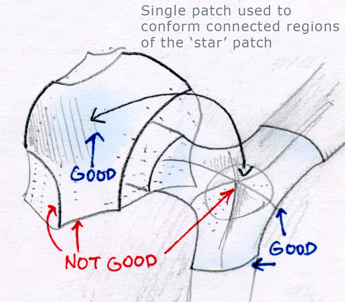
There you can pretty easily see the problems near the boundary edges - there's a bunch of bumps and the patch surface does not meet up with the adjacent surfaces totally tangent, there's a sharp area where they meet, particular at the top and bottom juncture areas.

There are similar problems with every single one of your other examples, here are some screenshots:


I've also tried some various test cases in ViaCAD myself and seen these same kinds of problems too, so I thought I'd ask you for your file to see if your own examples were of good quality or had these problems.

This is kind of troubling in general because I've sometimes thought that maybe I should license the ACIS geometry kernel to improve filleting in MoI, but if this is the best quality that the n-sided patch mechanism in ACIS can deliver I'm not sure that it will really be that great, although I guess an argument can be made that it's better to have this than nothing... and also some kinds of usage purposes like if you're making an STL/3D printed result the size of the lumps are small enough that they're probably less than the size of the printer resolution itself and so probably don't matter for that case. It's not nice for high quality rendering though.

It kind of turns out that MoI's high quality surface display is almost something of a curse in this situation - just the regular display without doing the high density export generates enough triangles that you can see these surface defects during regular modeling, while other CAD programs have such a lower density triangulation that these defects get obscured and many people are just unaware that there's a problem until maybe they try to export something to a renderer and make it reflective and see that it looks bad in a close-up in the renderer...

I guess that possibly a good n-sided patch mechanism is rarer than what I had previously thought. Or maybe just all these cases are just too difficult on it to handle very well, although even just doing a setback corner on a box has problems. The file valise.3dm posted at the very first message of this whole thread has a whole bunch of lumps and bumps all over it...

- Michael

EDITED: 8 Dec 2012 by MICHAEL GIBSON


  Reply Reply More Options
Post Options
Reply as PM Reply as PM
Print Print
Mark as unread Mark as unread
Relationship Relationship
IP Logged

Previous
Next
 From:  BurrMan
5590.20 In reply to 5590.19 
Here's a patch srface from rhino so you can turn on control points to see what it's doing. I still got a little "dip" in my tangent connections, but I think it was more of a poor choice for UV count to produce a good surface. I later tried 9x9, which was using the compound of 3 to get more equal. It "looked" like a better result. I would certainly have to study up on it to use it well.
Attachments:

  Reply Reply More Options
Post Options
Reply as PM Reply as PM
Print Print
Mark as unread Mark as unread
Relationship Relationship
IP Logged
 

Reply to All Reply to All


Show messages:  1-20  21-40  41-60  61-75