Printing a template to exact dimensions

Next
 From:  bemfarmer
5545.1 
Are there any suggestions for printing a 2d template on a laserjet printer, to the exact physical dimensions?
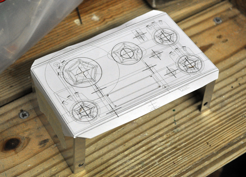
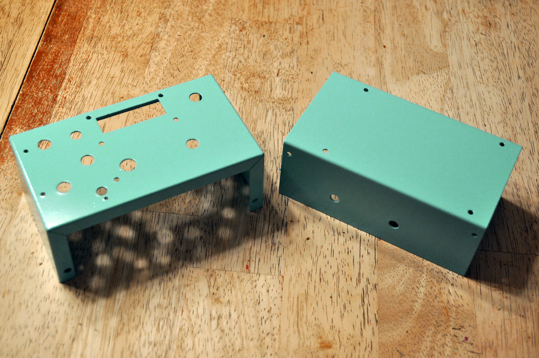
The paper template is to be glued to a piece of aluminum, as a centerpunch and drilling guide.
For example, a 6" by 6" plate, with 16 holes placed at 1.5".


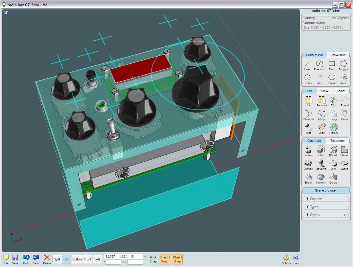
I ended up importing the .3dm 3d surface/object into Alibre. It went in with an unwanted small vertical displacment, and the drawing portion of Alibre did not work with it, so I ended up redrawing everything in Alibre, both due to my poor awkward inability with Alibre. Then used the Alibre drawing portion of the program to insert hole centers, and printed the 2d drawing exactly.

I did try a MoI dxf with draftsight, but quickly gave up.

So the Alibre method worked, but wondered if there were any other suggestions?
Attachments:

  Reply Reply More Options
Post Options
Reply as PM Reply as PM
Print Print
Mark as unread Mark as unread
Relationship Relationship
IP Logged

Previous
Next
 From:  Michael Gibson
5545.2 In reply to 5545.1 
Hi Brian, you might try exporting to AI format and using a 2D illustration program like Expression:
http://download.microsoft.com/download/a/5/d/a5d625a5-2e3d-4e9c-8608-6de48d7b569f/CreatureHouseExpression3_3.exe

Those are usually highly oriented around working with a printed result, so there's stuff like the page boundaries and rulers shown on the screen.

If you set units to be inches and then uncheck "fit to page" when you do the AI export it should preserve the unit size of your objects in the generated AI file.

- Michael
  Reply Reply More Options
Post Options
Reply as PM Reply as PM
Print Print
Mark as unread Mark as unread
Relationship Relationship
IP Logged

Previous
Next
 From:  bemfarmer
5545.3 In reply to 5545.2 
Thank you Michael. Will try it tomorrow.
  Reply Reply More Options
Post Options
Reply as PM Reply as PM
Print Print
Mark as unread Mark as unread
Relationship Relationship
IP Logged

Previous
Next
 From:  blowlamp
5545.4 In reply to 5545.1 
Here's a way I tried that seemed to work quite well.

In Scene browser, hide your solid part.

Then, move down to the Edges line and click the area where the eye icon resides. This will display a wireframe of the solid.

Still in scene browser, select all edges by moving to the right of the Edges line and clicking - so a yellow dot appears.

Press Ctrl-C folowed by Ctrl-V to copy and paste curve equivalents of the edges.

These curves can now be selected and exported at will to your other chosen application for further work or printing. I tried .dxf and .iges into ViaCAD and everything came through sweetly.


Martin (2).
  Reply Reply More Options
Post Options
Reply as PM Reply as PM
Print Print
Mark as unread Mark as unread
Relationship Relationship
IP Logged

Previous
Next
 From:  coi (MARCO)
5545.5 
oi there!

you could try solidworks edrawings viewer, which eats dxfs and puts out a 1 to 1 print. just tested it with a moi generated dxf in mm and it worked fine.

http://www.edrawingsviewer.com/


~marco

  Reply Reply More Options
Post Options
Reply as PM Reply as PM
Print Print
Mark as unread Mark as unread
Relationship Relationship
IP Logged

Previous
Next
 From:  Ralf-S
5545.6 
Hi Brian,

Start Moi3D and AD

Moi3D
Ctrl+C

AD
Ctrl+V
Image Attachments:
Size: 259.9 KB, Downloaded: 56 times, Dimensions: 1154x717px
  Reply Reply More Options
Post Options
Reply as PM Reply as PM
Print Print
Mark as unread Mark as unread
Relationship Relationship
IP Logged

Previous
Next
 From:  Ralf-S
5545.7 
AD -> Surfacing -> Stitch -> Stitch to Solid
Save...
Image Attachments:
Size: 146.4 KB, Downloaded: 28 times, Dimensions: 1041x721px
  Reply Reply More Options
Post Options
Reply as PM Reply as PM
Print Print
Mark as unread Mark as unread
Relationship Relationship
IP Logged

Previous
Next
 From:  Ralf-S
5545.8 
AD -> New Drawing ->
Image Attachments:
Size: 82 KB, Downloaded: 34 times, Dimensions: 1042x709px
  Reply Reply More Options
Post Options
Reply as PM Reply as PM
Print Print
Mark as unread Mark as unread
Relationship Relationship
IP Logged

Previous
Next
 From:  Mike K4ICY (MAJIKMIKE)
5545.9 
For you "home-brew"ers and DIY'ers doing small-scale projects. This method works fine:

I did as Michael suggested. I exported my Top view projection to an .ai file and brought it into a program like Corel or Illustrator.
I was then able to print the template out from my laser printer, which was subsequently taped on to the aluminum substraight I wanted to drill pilot holes into.


-Project-


Please note this possibly important nuance:

After two decades of outputting film for screen printing using a laser printer as the stencil maker, I know the all-too well, slight inaccuracies of using the laser medium. When registration becomes an issue, there are good reasons from media tracking discontinuities to the usually overlooked middle-to-sides physical sizing differences due to the fact that the laser is scanned to a flat surface from a point via a spinning mirror array where there becomes a slight conical displacement.

(whew).

But as you see from my examples, MoI still is a great way to get into some of your own basic engineering.
  Reply Reply More Options
Post Options
Reply as PM Reply as PM
Print Print
Mark as unread Mark as unread
Relationship Relationship
IP Logged

Previous
 From:  bemfarmer
5545.10 
Thankyou everyone, Michael, Ralf-S, Mike, Martin, Marco.
I count 5+ methods.
  Reply Reply More Options
Post Options
Reply as PM Reply as PM
Print Print
Mark as unread Mark as unread
Relationship Relationship
IP Logged
 

Reply to All Reply to All