Iso Curve

Next
 From:  BurrMan
5271.1 
Hi Michael,
I'm really liking the isocurve/isoparm command that was added.

I was wondering if you had some future development with it in the mix? I was thinking about some number inputs for the u,v and both quantities to cover a surface along with a tolerance or distance along surface value for spacing of the iso's?
  Reply Reply More Options
Post Options
Reply as PM Reply as PM
Print Print
Mark as unread Mark as unread
Relationship Relationship
IP Logged

Previous
Next
 From:  Michael Gibson
5271.2 In reply to 5271.1 
Hi Burr, I didn't really have anything else specific planned for it... Maybe it could be a good fit for a separate plug-in to do some more styles of generating them.

But re: cover a surface with a given spacing - the difficulty with that is that isocurves can easily have highly variable spacing in 3D distance between them, here's a quick example:


So notice there how that particular surface is wider at the ends and compressed in the middle area? Isocurves generated on it will correspond with that - any 2 isocurves from that surface do not have any fixed distance between them - in the compressed area of the surface there is a tighter spacing and in the wider ends there is a wider spacing in 3D space. In UV space they may have a constant distance in that space but that's different than an actual 3D distance measurement. You seem to be asking about giving one single 3D distance value but that does not really exist in all cases, only highly regular and very simple surfaces like a plane or extrusion would actually have that, and you can use an array tool to make repeated spaced stuff for those cases already actually.

- Michael

  Reply Reply More Options
Post Options
Reply as PM Reply as PM
Print Print
Mark as unread Mark as unread
Relationship Relationship
IP Logged

Previous
Next
 From:  Frenchy Pilou (PILOU)
5271.3 In reply to 5271.2 
No possibility to have the isocurves with "rotation" with the same process ?
Of course i can make some rotated projection of some grides lines....

EDITED: 22 Jul 2012 by PILOU

  Reply Reply More Options
Post Options
Reply as PM Reply as PM
Print Print
Mark as unread Mark as unread
Relationship Relationship
IP Logged

Previous
Next
 From:  BurrMan
5271.4 In reply to 5271.2 
Hi Michael,
I see. I WAS testing with more generic "squarish" networks and stuff. I was looking at using it to rebuild stuff. Even in the curved surface example you show though, I was looking for some type of "uniform coverage" method...
  Reply Reply More Options
Post Options
Reply as PM Reply as PM
Print Print
Mark as unread Mark as unread
Relationship Relationship
IP Logged

Previous
Next
 From:  Michael Gibson
5271.5 In reply to 5271.3 
Hi Pilou,

> No possibility to have the isocurves with "rotation" with the same process ?

Nope, not with this particular tool - if it was rotated it would actually no longer be an "Isocurve" but just a more generic UV curve. An Isocurve specifically means a UV curve that is horizontal or vertical in UV space.


> Of course i can make some rotated projection of some grides lines....

Or also if you want to have any generic UV curves applied to your surface you can create a plane with the curves arranged on it and then use the Flow command to map those onto the surface.

- Michael
  Reply Reply More Options
Post Options
Reply as PM Reply as PM
Print Print
Mark as unread Mark as unread
Relationship Relationship
IP Logged

Previous
Next
 From:  Michael Gibson
5271.6 In reply to 5271.4 
Hi Burr,

> Even in the curved surface example you show though, I was looking for
> some type of "uniform coverage" method...

How would you expect to get uniform coverage on a fundamentally non-uniform surface though?

Are you maybe thinking of something more like planar section lines? That's a different kind of a thing than isocurves - you can get planar section cut lines by making an array of lines and then using Project.

The part that is useful with an isocurve is that they have a sort of natural alignment to the surface, so for example an isocurve in one direction on a fillet surface will be an arc curve, and using isocurve will let you easily extract that arc.

- Michael
  Reply Reply More Options
Post Options
Reply as PM Reply as PM
Print Print
Mark as unread Mark as unread
Relationship Relationship
IP Logged

Previous
Next
 From:  Michael Gibson
5271.7 In reply to 5271.4 
Hi Burr, also -

> Even in the curved surface example you show though, I was looking for some type of "uniform coverage" method...

If you wanted something that was a bunch of curves uniform in UV space but then created as 3D isocurves you could do that using Flow - set up a plane with a pattern of lines on the plane however you want them arranged in UV space and then use Flow to map them from that plane onto the curved surface.

Flow can work with a batch of lines so it might be better suited for what you are thinking about.

- Michael
  Reply Reply More Options
Post Options
Reply as PM Reply as PM
Print Print
Mark as unread Mark as unread
Relationship Relationship
IP Logged

Previous
Next
 From:  Frenchy Pilou (PILOU)
5271.8 In reply to 5271.5 
<< create a plane with the curves arranged on it and then use the Flow command to map those onto the surface.

Cool !
---
Pilou
Is beautiful that please without concept!
My Gallery
  Reply Reply More Options
Post Options
Reply as PM Reply as PM
Print Print
Mark as unread Mark as unread
Relationship Relationship
IP Logged

Previous
Next
 From:  BurrMan
5271.9 In reply to 5271.7 
Flow does it, but with no, or difficult control of the spacing. But at this point, I'm not sure the spacing value is relevant at all...

Talk later.
  Reply Reply More Options
Post Options
Reply as PM Reply as PM
Print Print
Mark as unread Mark as unread
Relationship Relationship
IP Logged

Previous
Next
 From:  Michael Gibson
5271.10 In reply to 5271.9 
Hi Burr, any method that starts with UV curves and then evaluates those into 3D will have the exact same issue as using Flow.

It seems that maybe you want a completely different construction method rather than one that comes from UV space which is also what the Isocurve command is focused on.

I guess I'd need to see some examples of what kind of results you would expect to get on non-uniformly shaped surfaces like the "bow tie" type thing that I posted earlier. Do you want planar cut lines with spaces between the cut planes? If so then that is different from UV based construction and you can get that currently by making an array of lines and using Construct > Curve > Project.

If you don't want that either then I guess I need to have some more explanation of what you want. It's not clear to me that it's physically possible to do what you are mentioning but if you can maybe make some examples and describe it in more detail that may help me to understand it better.

Surfaces are tricky things to handle with "constant spacing" since they can be dynamically stretching and compressing in all sorts of ways and can have totally different lengths across them in different regions of the surface.

There's also different ways of even measuring what you mean by distance between things - for example on any 2 points on the surface you could either measure the direct distance between those 2 points (as if they were joined by a straight line) or you could also measure the distance that would be traveled by walking from one to the other while staying on the surface.

- Michael
  Reply Reply More Options
Post Options
Reply as PM Reply as PM
Print Print
Mark as unread Mark as unread
Relationship Relationship
IP Logged

Previous
Next
 From:  Mike K4ICY (MAJIKMIKE)
5271.11 
I suggest to make you series of curves in a non-3d view and Project them to the surface.

There was a technique shown not long ago where one user created a smoothly transitioned steps of curves from one to the other using Sweep.
  Reply Reply More Options
Post Options
Reply as PM Reply as PM
Print Print
Mark as unread Mark as unread
Relationship Relationship
IP Logged

Previous
Next
 From:  Mike K4ICY (MAJIKMIKE)
5271.12 
Take note:

The distribution of U/V coordinates on a surface is based on the special distribution attributes found in the creation splines makeup.

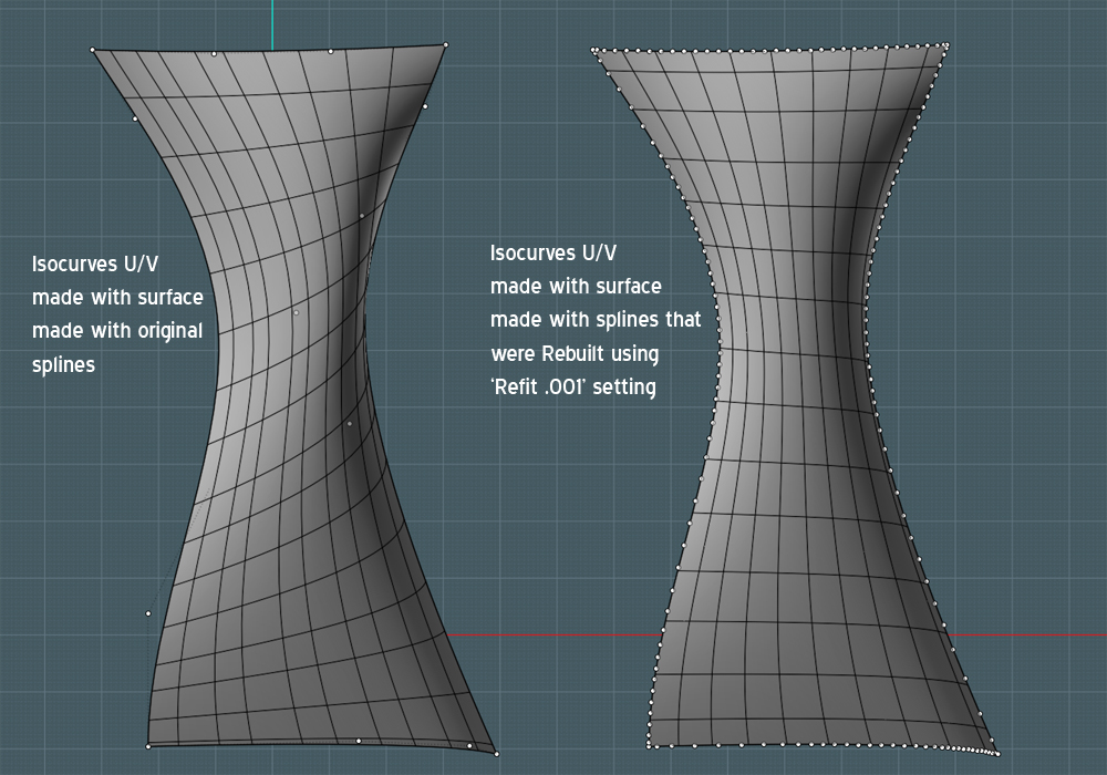
In the following pic: The surface on the left was created with splines made originally with the FreeForm tool.

The splines themselves were copied to the right and the 'Rebuild' command was run. The mode of 'Refit' was chosen, and in this tolerance of 0.001 was used in this example.
As you can see, there are more points defining the splines, but really what has happened here was that the splines have now been refit with internal attributes that make them 'flow' with a more physically even distribution.

With the surface Networked from these splines, you can see that the distribution of the Isocurves U/V are more 'logical' and even in appearance.


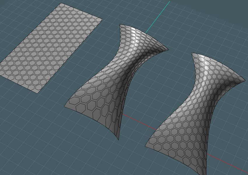
This 'Rebuild' process also applies for Flow tool use.

EDITED: 22 Jul 2012 by MAJIKMIKE

  Reply Reply More Options
Post Options
Reply as PM Reply as PM
Print Print
Mark as unread Mark as unread
Relationship Relationship
IP Logged

Previous
 From:  Frenchy Pilou (PILOU)
5271.13 In reply to 5271.12 
Good to know!
---
Pilou
Is beautiful that please without concept!
My Gallery
  Reply Reply More Options
Post Options
Reply as PM Reply as PM
Print Print
Mark as unread Mark as unread
Relationship Relationship
IP Logged
 

Reply to All Reply to All