PET Bottle?

Next
 From:  suman
5147.1 
hello together

can someone tell me how to create a plastic PET bottle in MoI?
I have very trouble with the ground :-/


Attachments:

  Reply Reply More Options
Post Options
Reply as PM Reply as PM
Print Print
Mark as unread Mark as unread
Relationship Relationship
IP Logged

Previous
Next
 From:  Michael Gibson
5147.2 In reply to 5147.1 
Hi suman, check out Mike's tutorials here for a couple of different bottles:
http://www.k4icy.com/tutorials.html

Those may help with other kinds of features, but I don't think that it has that particular kind of bottom feature that you're asking about - I'll see about making a small example for that.

- Michael
  Reply Reply More Options
Post Options
Reply as PM Reply as PM
Print Print
Mark as unread Mark as unread
Relationship Relationship
IP Logged

Previous
Next
 From:  Mike K4ICY (MAJIKMIKE)
5147.3 
Hi Sunan!

Why I'll just whip a tutorial right up - it's why they call me "Magic"! ;-)
Ah, yes...


There are many ways that NURBS solid modeling can go about this shape, and MoI can surely fit the bill.

Here is a quick tutorial that can create the shape you're looking for in just a few easy steps:

The method I'll use here works with Profile Curves and Profile Rings, to be used with the Network command, which I call a "Complex Axial Surface"
Visit my tutorial here to see a more in-depth discussion - http://moi3d.com/forum/index.php?webtag=MOI&msg=4610.1

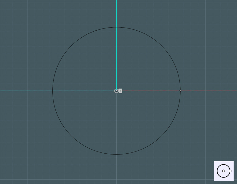
First, draw the circles derived from the body of the bottle you're working with...


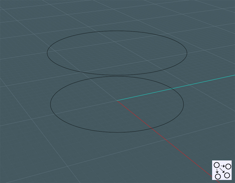
Then, make a copy to start generalizing you shape...


Now, go to a side view and create profile curves using one of your curve tools...


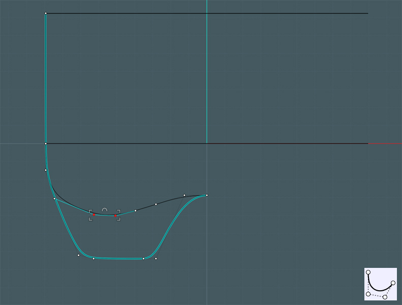
Notice how I made a copy and then used Show Points to allow me to move some of the control points.
The taller profile represents the foot of the bottle base, and the shorter will become the recessed area.


Next, we need to Array copies of these profiles...

I made three adjacent copies of the foot profile curve so that when Networked, it will become more flat where these shapes are repeated.
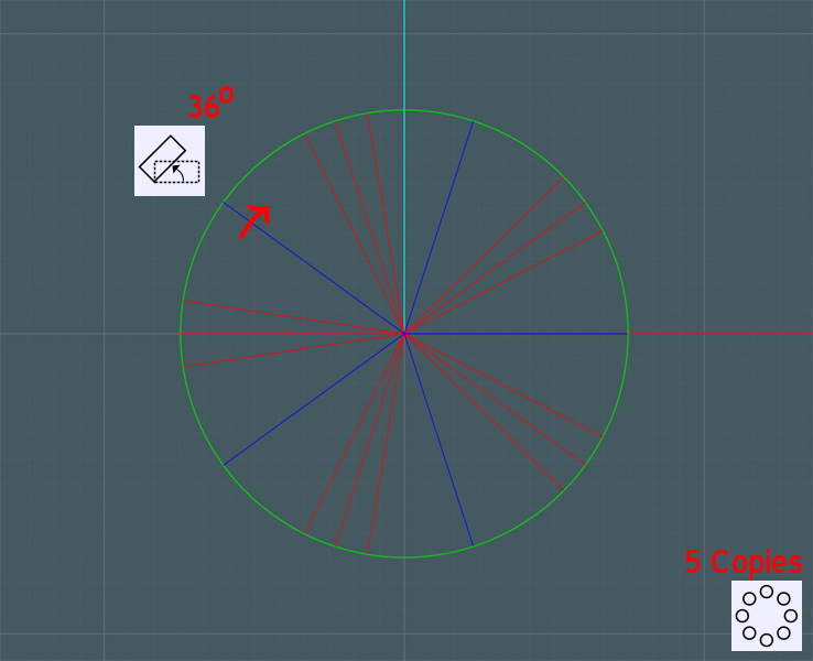
I Circular Arrayed the foot profile set five times around the center axis.

The blue curve shown here, is the shorter recessed profile. To move it exactly in-between the foot profile sets, I used Rotate (from the center axis) to rotate the blue line 36 degrees.
(360/5/2)
When Circular Arrayed five times also, that profile fit in sequence with the foot profile set.


It is a good idea to make more copies of the profile ring. I'll use Copy and then Scale 2-D to place these closely along the general shape of my profile curves.
Network will create an averaged surface based on where these curves go. The closer to the end shape they are, the cleaner it will look.


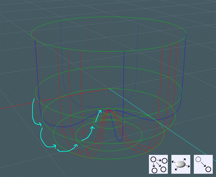
Of course, you can go back and alter the curve shapes and ring placement to suit the final result (as I have).

Select all the rings and curves and run the Network command...
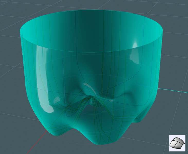


Here you go!


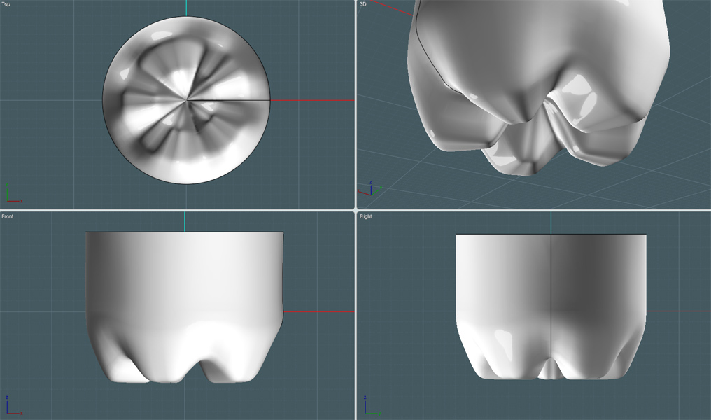
Mind you, this is a little rough, of course for tutorial purposes.
You can do a few things to tweak your Network surface for better effect.
A little Boolean and Blend work may only help as well.


I hope this tutorial helped.

Mike
  Reply Reply More Options
Post Options
Reply as PM Reply as PM
Print Print
Mark as unread Mark as unread
Relationship Relationship
IP Logged

Previous
Next
 From:  Michael Gibson
5147.4 In reply to 5147.1 
  Reply Reply More Options
Post Options
Reply as PM Reply as PM
Print Print
Mark as unread Mark as unread
Relationship Relationship
IP Logged

Previous
Next
 From:  Michael Gibson
5147.5 In reply to 5147.1 
Another possible technique is to model a sort of "scallop" surface and then use a boolean to cut that material away from the base solid, and then you follow that with a fillet to round off the edges.

That looks something like this - some sort of profile and path curve similar to this:


A surface can then be constructed from those using sweep - select the bottom one first to be the profile curve, then run Construct > Sweep and pick the other one as the rail path. That builds a surface like so:


This surface relates to the main body in this way, note how it is extends all the way through the body so that it will be able to cut it:


Use Transform > Array > Circular to replicate it around into a circular pattern:


Now select the main body and run Construct > Boolean > Difference, and pick those scallop surfaces as the cutting objects. That will slice the main body with those surfaces and result in several pieces, select these pieces:


And then delete those objects, leaving just the big piece behind:


Then use Construct > Fillet to round off those edges:


I hope this gives you the general idea - you can alter the shape quite a bit by adjusting the curves that were used for constructing the scallop, to make the scallop narrower or longer or angle it differently or whatever. Also you may want to slice out another piece from the center core, maybe use a revolve on a profile curve to make a sort of dome to boolean away for that.

But anyway, you can use cutting objects in this fashion to slice away chunks and that then forms the feet out of the remaining areas.

- Michael

  Reply Reply More Options
Post Options
Reply as PM Reply as PM
Print Print
Mark as unread Mark as unread
Relationship Relationship
IP Logged

Previous
Next
 From:  Mike K4ICY (MAJIKMIKE)
5147.6 
The possibilities are nearly endless! :-)
  Reply Reply More Options
Post Options
Reply as PM Reply as PM
Print Print
Mark as unread Mark as unread
Relationship Relationship
IP Logged

Message 5147.7 deleted 23 May 2012 by SUMAN

Previous
Next
 From:  bigseb
5147.8 
Here is a bottle I did a while back. Uses the same method that Michael suggests. Remember: there are no rules. All that matters is how it looks.

Attachments:

  Reply Reply More Options
Post Options
Reply as PM Reply as PM
Print Print
Mark as unread Mark as unread
Relationship Relationship
IP Logged

Previous
Next
 From:  TwinSnakes
5147.9 
Took me a while, but this method of defining rough shapes and then filleting, finally clicked in my head last week when I was modelling a cell phone. I started out trying to lay down some contour curves, but it quickly got difficult to manage. So I started over and just roughly blocked out some shapes and then applied a fillet. It's a much faster workflow and it made me look smarter than I actually am. :-]
  Reply Reply More Options
Post Options
Reply as PM Reply as PM
Print Print
Mark as unread Mark as unread
Relationship Relationship
IP Logged

Previous
Next
 From:  Frenchy Pilou (PILOU)
5147.10 In reply to 5147.9 
< just roughly blocked out some shapes and then applied a fillet.

That is the secret !
---
Pilou
Is beautiful that please without concept!
My Gallery
  Reply Reply More Options
Post Options
Reply as PM Reply as PM
Print Print
Mark as unread Mark as unread
Relationship Relationship
IP Logged

Previous
Next
 From:  Michael Gibson
5147.11 In reply to 5147.9 
Hi TwinSnakes, that's great that method is clicking!

It takes a while to get used to it - basically when you look at a shape and there is some mixture of broad shapes and then some more tightly bent areas try to temporarily ignore the tightly bent transition areas since those are indicative of fillets.

The other kind of thing is not getting too focused on building surfaces that directly hug to some irregular outline - usually you want to build an extended surface and then cut it rather than trying to construct the surface initially to such an outline. That kind of thing with visualizing extended areas of the model earlier on in the process can sometimes take a while to get the hang of as well.

- Michael
  Reply Reply More Options
Post Options
Reply as PM Reply as PM
Print Print
Mark as unread Mark as unread
Relationship Relationship
IP Logged

Previous
 From:  suman
5147.12 
Many thanks for your help. I am very grateful for the solution paths
  Reply Reply More Options
Post Options
Reply as PM Reply as PM
Print Print
Mark as unread Mark as unread
Relationship Relationship
IP Logged
 

Reply to All Reply to All