Majik Widget Challenge: Utility Box
 1-20  21-40  41-60  61-78

Previous
Next
 From:  TpwUK
5119.41 In reply to 5119.40 
I like it - I like it a lot. The seam needs some attention as you can see orange poking through. Needs a lip or an L type lip on both edges.

Martin
  Reply Reply More Options
Post Options
Reply as PM Reply as PM
Print Print
Mark as unread Mark as unread
Relationship Relationship
IP Logged

Previous
Next
 From:  Mauro (M-DYNAMICS)
5119.42 In reply to 5119.41 
You mean to do the visible orange seal i made in the middle of the mic in the radio box too?You're right !(thanks for suggestion)
Please tell me if i understand right what you mean
..anyway if you check the mic file you'll can find not all correct and orthogonal,because i start modeling the mic in hurry
i'm always focused on the shape and the look of it,i leave little details and many times i'm plan just a little.This is wrong..i know..(this means when i say "istinctive approach)..
this CB transmitter is just a little part of my bigger project i'm working on
  Reply Reply More Options
Post Options
Reply as PM Reply as PM
Print Print
Mark as unread Mark as unread
Relationship Relationship
IP Logged

Previous
Next
 From:  Rich_Art
5119.43 In reply to 5119.40 
Awesome...


Peace,
Rich_Art. ;-)

| C4DLounge.eu | Our Dutch/Belgium C4D forum. |
  Reply Reply More Options
Post Options
Reply as PM Reply as PM
Print Print
Mark as unread Mark as unread
Relationship Relationship
IP Logged

Previous
Next
 From:  TpwUK
5119.44 In reply to 5119.42 
Sorry did not explain well enough


Attachments:

  Reply Reply More Options
Post Options
Reply as PM Reply as PM
Print Print
Mark as unread Mark as unread
Relationship Relationship
IP Logged

Previous
Next
 From:  Mauro (M-DYNAMICS)
5119.45 In reply to 5119.44 
I think is a unique camera angulation that show this ugly thing..if i choose all others point of views it not happens
screenshot of C4D scene without top box
you can see original Mike's rubber seal in correct position,not off-center

Photobucket

I have to leave the shot as it is....(wife is comin'home...better to stay as far as possible from PC..)
  Reply Reply More Options
Post Options
Reply as PM Reply as PM
Print Print
Mark as unread Mark as unread
Relationship Relationship
IP Logged

Previous
Next
 From:  Mike K4ICY (MAJIKMIKE)
5119.46 
M-dynamics, that's absolutely brilliant!!!
Really nice job on the renders and added augmentations and arrangement concepts.
It appears that this radio is virtually indestructible - and, might I add: weather-proof.

> Please forgive me Mike.i'm absolutely ignorant about CB Radioamateur stuff

No worries, a major attraction to the amateur radio hobby is the fun and creativity that is had.

You should see this little quick project of mine:
I mean, I used an Altoids mint tin as the case!


Also, the shape in between the two halves of the box was intended to be a rubber seal.
Since I didn't invest any time on the modeling of the interior, there are some coinciding surfaces that may render with unexpected results.
  Reply Reply More Options
Post Options
Reply as PM Reply as PM
Print Print
Mark as unread Mark as unread
Relationship Relationship
IP Logged

Previous
Next
 From:  SteveMacc (STEVEH)
5119.47 
Neat project Majik. I made a CW transceiver in a tobacco tin with discrete components. Yours looks too complex to be CW only. SSB? Also, did you make the board yourself?
  Reply Reply More Options
Post Options
Reply as PM Reply as PM
Print Print
Mark as unread Mark as unread
Relationship Relationship
IP Logged

Previous
Next
 From:  Mike K4ICY (MAJIKMIKE)
5119.48 In reply to 5119.47 
> Yours looks too complex to be CW only. SSB? Also, did you make the board yourself?

CW only. And it was a kit. It's circuitry design is over-designed for the type of method it uses, but it works well.
Steve, Check this out:

http://www.k4icy.com/cw.htm
- lower in the page.


And also:
http://www.k4icy.com/cw_qrp_sw40.html


The one in the mint tin is a KD1JV DC30 sold as a kit from Hendrix Kits. http://www.qrpkits.com/
It a single frequency rig with 1 watt output.
I happened on it from a friend learning how to solder. It looked really bad and I had to fix and re-do a bunch of stuff.

The pretty one is a CW rig that is an amalgam of different kits built from scratch. The main rig board is an SW40 that was until recently, sold by Small Wonder Labs. http://www.smallwonderlabs.com/
It boasts a 2 watt output. I put all kinds of other goodies in, including a digital display and keyer module. It tunes all of the 7 mHz CW ham band and has a very good receiver.

You'll also see that I used MoI to design the exact placement of all of the main components and panel hole placements.

Of course, I could fire up my commercial rig and send CW at 100 watts, but what many don't know is that just a few watts are enough to span the globe with good conditions. And there's a sport to that.
I've also built a few relatively basic circuits containing just a handful of parts. All fun.
  Reply Reply More Options
Post Options
Reply as PM Reply as PM
Print Print
Mark as unread Mark as unread
Relationship Relationship
IP Logged

Previous
Next
 From:  Mauro (M-DYNAMICS)
5119.49 
At the beginning of this thread you told about glitches,i checked one more time the rubber seal.Moi says that's a joined surface,not a solid(is better to have solids,more warranties to have all surfaces welded together)
..no problem Mike,maybe i'll do another shot leave things as they are,retouching later in PS !


Photobucket
  Reply Reply More Options
Post Options
Reply as PM Reply as PM
Print Print
Mark as unread Mark as unread
Relationship Relationship
IP Logged

Previous
Next
 From:  Michael Gibson
5119.50 In reply to 5119.49 
Yeah it looks like that edge is not joined between those 2 surfaces - when edges are joined the generated mesh combines together vertex structures of both sides of the joined edge to avoid those kinds of cracks.

- Michael
  Reply Reply More Options
Post Options
Reply as PM Reply as PM
Print Print
Mark as unread Mark as unread
Relationship Relationship
IP Logged

Previous
Next
 From:  Lejan
5119.51 


As I could not get any clear .obj import into KeyShot, smashing in ZBrush and blurring in PShop helped hiding the lack of
my modelling skills... ;) And no, Yoda is just a bitmap... :)
Attachments:

  Reply Reply More Options
Post Options
Reply as PM Reply as PM
Print Print
Mark as unread Mark as unread
Relationship Relationship
IP Logged

Previous
Next
 From:  Mike K4ICY (MAJIKMIKE)
5119.52 
LOL!!!!!!! Creative, Lejan!

"If you can't fix it, caulk it" is what the contractors say.


> rubber seal.Moi says that's a joined surface,not a solid...

M, you are right:


You can see where the tessellated polygons do not come together and do not match.

Michael, these surfaces said they were joined, but upon closer examination, when you separate the whole object set and try to join the surfaces in question separately, they refuse to.

To let you know the possible reason, the method for their creation involved Lofting a surface between two closed curves that were duplicated from the edges of the top and bottom surfaces of the seal shape.
As I have discovered, Loft uses some type of interpolation, which means that the new Lofted surface intended to become the sides may have been an in-approximate representation of the large surfaces they were created to link.

Here is how I went about fixing it: I separated these surfaces to free-standing pieces. I tried to Join those two surfaces in question, but they still refused. I can gather that the edge curves that define these two supposedly adjacent surfaces do not actually run the same course, and have some minute separation between them. This is where the command "MatchSrf" would have been king!
I was under impression that Join was good a working around these "near misses".
So, I took these two surfaces and performed a Boolean Union. They are now one joined surface as shown here:


As you can see here, when exported, the polygons are now "matched" together and connected with no peering seam.

Michael, I'd like to know a little about how Boolean Union lined these two edges up. Maybe they actually crossed?
I invite you to also look at those surfaces in the provided model.

This has actually been a good event in this project. It's nice to find problems that arise in the modeling process and then figure ways to remedy them.

EDITED: 13 May 2012 by MAJIKMIKE

  Reply Reply More Options
Post Options
Reply as PM Reply as PM
Print Print
Mark as unread Mark as unread
Relationship Relationship
IP Logged

Previous
Next
 From:  BurrMan
5119.53 In reply to 5119.52 
We're having a "party in a box".........I think we'll leave the other part out!

EDITED: 19 Jun 2012 by BURRMAN

  Reply Reply More Options
Post Options
Reply as PM Reply as PM
Print Print
Mark as unread Mark as unread
Relationship Relationship
IP Logged

Previous
Next
 From:  TpwUK
5119.54 In reply to 5119.53 
BurrMan, you have way too much time on your hands - lol :)

Martin
  Reply Reply More Options
Post Options
Reply as PM Reply as PM
Print Print
Mark as unread Mark as unread
Relationship Relationship
IP Logged

Previous
Next
 From:  BurrMan
5119.55 In reply to 5119.54 
""""""""""""""BurrMan, you have way too much time on your hands - lol""""""""""

Actually, no. Thats why no modeling and just a party slapped together. (Although I did flow the little guy, in honor of majik.)
  Reply Reply More Options
Post Options
Reply as PM Reply as PM
Print Print
Mark as unread Mark as unread
Relationship Relationship
IP Logged

Previous
Next
 From:  Mike K4ICY (MAJIKMIKE)
5119.56 
Wellll I like it!!! ;-)

There's no denying it, what better way to chillax away a hard day than with the MoI Brand Portable Luau System!
  Reply Reply More Options
Post Options
Reply as PM Reply as PM
Print Print
Mark as unread Mark as unread
Relationship Relationship
IP Logged

Previous
Next
 From:  Michael Gibson
5119.57 In reply to 5119.52 
Hi Mike,

> Michael, these surfaces said they were joined, but upon closer examination, <...>

You can have surfaces that are joined together into a larger connected chunk of an object, while still having some various particular edges in there not joined to one another.

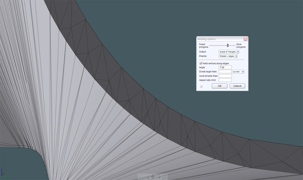
Here's an example to clarify:


That object is a "joined srf" because a "joined srf" just means that the object in question is made up of more than one surface joined together.

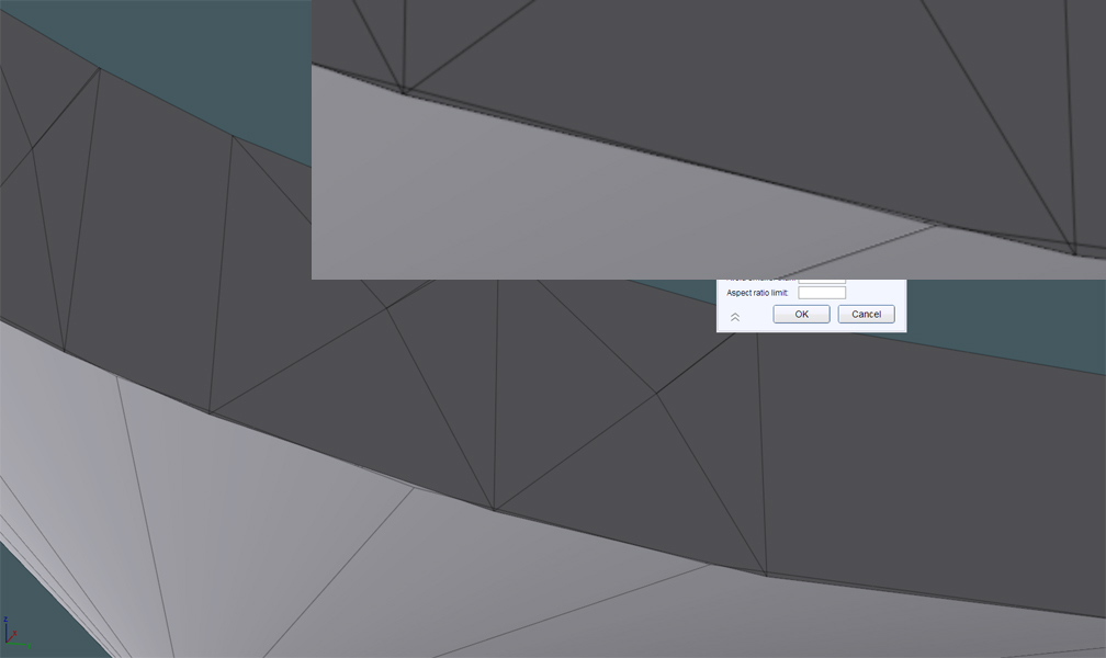
In this case the joined edges are these ones here:


This area here on the other hand did not get joined because there is too much of a space between the different surface edges there:


So that's the same kind of thing that you have there.

When the object type is "Joined srf" it doesn't mean that every edge is joined - in fact it actually means the opposite of that, that only some edges are joined and some are not, because if every single edge is joined to another one that will be labeled as a "solid" instead of "joined srf".


> when you separate the whole object set and try to join the surfaces
> in question separately, they refuse to.

This usually means that the particular edges have too large of a gap between them - the edges must have a maximum distance of only 0.005 units between them in order for them to get joined together.


> As I have discovered, Loft uses some type of interpolation, which means that the new
> Lofted surface intended to become the sides may have been an in-approximate
> representation of the large surfaces they were created to link.

By default Loft will do an automatic rebuild on each of the profile curves, that can generally help to even out the parameterization of the profiles before they become surface-ized and also to give all the profiles an inherently compatible parameterization which helps to make the final Loft result not be so dense with knots and control points. You can disable that by using the "Profiles" option in Loft - if you use Profiles: Exact then there won't be any interpolation/approximation step at all and the loft will go exactly through the profile without any rebuilding involved. But the Exact mode also means that the resulting surface's knot vector will contain the combination of the knot vector from every single profile curve together and also the surface will inherit any non-uniform parameterization so things like control point spacing can cause the loft surface to bunch or stretch.

But the rebuild step is supposed to rebuild to a tolerance of 0.001 units (unless you have set # of points mode of the profiles which does a much less accurate but also less dense resulting approximation), so it is supposed to be accurate enough to give a joinable result. If that's not happening then that may be a bug in the curve fitter - is it possible for you to boil it down to a simplified example of that problem, like just a file containing 3 curves in it and lofting between 2 of them at a time to generate a surface then does not join? If I had a reproducable example like that then I could probably verify if it is a bug or what.


> I was under impression that Join was good a working around these "near misses".

It is, up to a gap size of 0.005 - if your gap size is somethign like 0.006 units that's still pretty small visually and hard to see the gap without zooming in closely to the area where it is the largest.


> As you can see here, when exported, the polygons are now "matched" together and
> connected with no peering seam.

So that means that there is now a proper joined edge there now.


> Michael, I'd like to know a little about how Boolean Union lined these two edges
> up. Maybe they actually crossed?
> I invite you to also look at those surfaces in the provided model.

I'm not really following exactly what was booleaned. There does not seem to be any model attached to that particular message - in order for me to really follow along with what you are describing I'll need to have a more simplified result, like 2 objects set up to do a boolean union, then I can do the union and see the result rather than trying to reverse engineer some final result model for example.

Right now without simplified examples I just don't quite know the precise answers to your questions because it's hard for me to figure things out just looking at some big pile of surfaces - I don't know where to look or which particular spot the problem is in, etc.. etc...

So if you can simplify things, like "here are 3 curves, when lofted in pairs they don't join", or "here are 2 objects, when booleaned unioned can you give me some more information about the result in this spot here", etc.. would make it so I could better understand stuff and give more information back.

- Michael

  Reply Reply More Options
Post Options
Reply as PM Reply as PM
Print Print
Mark as unread Mark as unread
Relationship Relationship
IP Logged

Previous
Next
 From:  Michael Gibson
5119.58 In reply to 5119.52 
Hi Mike, also is it possible that instead of Loft you used Network on the things that don't join and you're also using version 2?

The Network command also does an automatic rebuild of the input curves, but in v2 it did it to a lower tolerance which could sometimes make results that were just a little bit out of join tolerance. That should be tightened up in v3 though.

- Michael
  Reply Reply More Options
Post Options
Reply as PM Reply as PM
Print Print
Mark as unread Mark as unread
Relationship Relationship
IP Logged

Previous
Next
 From:  BurrMan
5119.59 In reply to 5119.58 
Hi Michael,
"""""""""> I was under impression that Join was good a working around these "near misses".

It is, up to a gap size of 0.005 - if your gap size is somethign like 0.006 units that's still pretty small visually and hard to see the gap without zooming in closely to the area where it is the largest.""""""""""""""

So then when using this method to join "pretty close stuff" would it then succed if you used a scaling workflow and scaled "down, then back up" after the join?

Kindof like the opposite of getting a fillet in a very tiny area by scaling up 10 times.
  Reply Reply More Options
Post Options
Reply as PM Reply as PM
Print Print
Mark as unread Mark as unread
Relationship Relationship
IP Logged

Previous
Next
 From:  Michael Gibson
5119.60 In reply to 5119.59 
Hi Burr,

> So then when using this method to join "pretty close stuff" would it then
> succed if you used a scaling workflow and scaled "down, then back up"
> after the join?

Yeah usually that does work, because when the geometry is scaled down the gaps between edges are scaled down as well and that can put them under the join tolerance at that point.

You don't want to scale it down too much though because Join does use the relative tolerance mechanism so things below 1 unit in size in their bounding box diagonal will use a fraction of that diagonal size rather than an actual fixed 0.005 unit value.

So you'd want to scale down by 1/10 in size probably and then scale up after the join.

- Michael
  Reply Reply More Options
Post Options
Reply as PM Reply as PM
Print Print
Mark as unread Mark as unread
Relationship Relationship
IP Logged
 

Reply to All Reply to All


Show messages:  1-20  21-40  41-60  61-78