Testing v3 for vehicle modelling
 1-11  12-31  32-51  52-71  72-91  92-111  112-116

Previous
Next
 From:  TpwUK
5101.52 In reply to 5101.51 
Forgive my ignorance I seem to have over complicated things again ...

I thought a simple plane with a decal image that could be tilted/rotated on all axis combined with the zoom and pan options might have been enough to do a crude camera match. Being able to scale one side of the plane as required so as to create rhomboidal shapes to help with perspective issues.

It was just a thought, but as is often the case, a not very well thought out one - Lol

All the best Michael

Martin
  Reply Reply More Options
Post Options
Reply as PM Reply as PM
Print Print
Mark as unread Mark as unread
Relationship Relationship
IP Logged

Previous
Next
 From:  Michael Gibson
5101.53 In reply to 5101.52 
Hi Martin, yeah I don't think it's really feasible to do a camera match calculation just purely from image adjustments like that, from what I have seen (I have not implemented one before myself actually though) it usually involves things more like analyzing stuff in the image itself possibly including things like user guided annotations or selecting matching points between 2 photos or things of that nature.

In any case since I'm not actually 100% familiar with all the details it would involve a lot of research as a first step before even actually digging into it.

Then like I mentioned before there would likely be a lot of UI to control the whole process and in general UI design for me tends to be a highly time consuming area of work.

So yeah I would expect for it to be a quite significant undertaking in order to do that.

For rendering programs it makes sense to have it for a focus area since it's frequently needed there to merge the result of the rendering into an existing photo. So if you do want to do some kind of camera matching work you may want to look at a rendering program which has that feature in it already. If you are able to use a different program to calculate the camera position that matches a particular photo, it is possible to then set that camera position in MoI by using a script on a keyboard shortcut, see here for an example:
http://moi3d.com/forum/index.php?webtag=MOI&msg=2396.11

- Michael
  Reply Reply More Options
Post Options
Reply as PM Reply as PM
Print Print
Mark as unread Mark as unread
Relationship Relationship
IP Logged

Previous
Next
 From:  TpwUK
5101.54 
@ Michael - Thanks for given it some consideration Michael ... It was just an idea. As you say the more heavily bloated and expensive rendering suits do tend to be where the camera matching is, other than Blender, which to be honest i cant use for modelling ... Too cumbersome. I can live without it but it would have been nice to have something like it in a pure modelling package.

Otherwise here's a quick update on how things are going. For rendering purposes those fans in the back-end are good enough, but they are a mish mash of parts that wont marry up so will need to be re-done at some stage.

Martin
Image Attachments:
Size: 226.1 KB, Downloaded: 29 times, Dimensions: 1487x709px
  Reply Reply More Options
Post Options
Reply as PM Reply as PM
Print Print
Mark as unread Mark as unread
Relationship Relationship
IP Logged

Previous
Next
 From:  Mauro (M-DYNAMICS)
5101.55 In reply to 5101.54 
My message for all car modelers:

when you'll render your car please don't do this,remember your efforts when model,don't waste it


Translate the video title:MOST UGLY FERRARI OF THE WORLD
i'm a weird open -mind,but not to this limit
he thinks to be cool..but he isn't
  Reply Reply More Options
Post Options
Reply as PM Reply as PM
Print Print
Mark as unread Mark as unread
Relationship Relationship
IP Logged

Previous
Next
 From:  TpwUK
5101.56 In reply to 5101.55 
Yugh! That's one ugly Ferrari !

Thanks for the heads up

Martin
  Reply Reply More Options
Post Options
Reply as PM Reply as PM
Print Print
Mark as unread Mark as unread
Relationship Relationship
IP Logged

Previous
Next
 From:  TpwUK
5101.57 
Not much done again today, but i am busy doing other stuff ... Little updates, Front grill added,(but then exported out), side mirrors done, rear light clusters modelled ... File size is now approaching 20mb in size and the screen is beginning to stutter on rotations even without the grills - But most of the model is done now, not many surfaces to add but lots of fillets and blends to come yet.

Martin
Image Attachments:
Size: 144.1 KB, Downloaded: 21 times, Dimensions: 1213x723px
Size: 211.5 KB, Downloaded: 30 times, Dimensions: 1191x683px
  Reply Reply More Options
Post Options
Reply as PM Reply as PM
Print Print
Mark as unread Mark as unread
Relationship Relationship
IP Logged

Previous
Next
 From:  Frenchy Pilou (PILOU)
5101.58 In reply to 5101.57 
You have not planifid to make the engine ?
---
Pilou
Is beautiful that please without concept!
My Gallery
  Reply Reply More Options
Post Options
Reply as PM Reply as PM
Print Print
Mark as unread Mark as unread
Relationship Relationship
IP Logged

Previous
Next
 From:  TpwUK
5101.59 In reply to 5101.58 
My modelling skills are not up to that kind of accuracy yet - This project is to get a good body shape only and for me to test MoI on file sizes and ability to cope with medium detail level - I am dreading the wheels but at least i know where to come to for help if i get stuck. Once all the modelling is complete then it's export and import time with Blender Cycles as the target rendering engine to see how good that is too!

Martin
  Reply Reply More Options
Post Options
Reply as PM Reply as PM
Print Print
Mark as unread Mark as unread
Relationship Relationship
IP Logged

Previous
Next
 From:  BurrMan
5101.60 In reply to 5101.57 
"""""""""File size is now approaching 20mb in size and the screen is beginning to stutter on rotations even without the grills - """"""""""""""

Crank up the view angle time..... 20 or 30.
  Reply Reply More Options
Post Options
Reply as PM Reply as PM
Print Print
Mark as unread Mark as unread
Relationship Relationship
IP Logged

Previous
Next
 From:  TpwUK
5101.61 In reply to 5101.60 
Upping the mesh angle works fine too for looking around - might pay to script up some function buttons to adjust mesh angle on the fly - lol

Martin
  Reply Reply More Options
Post Options
Reply as PM Reply as PM
Print Print
Mark as unread Mark as unread
Relationship Relationship
IP Logged

Previous
Next
 From:  Michael Gibson
5101.62 In reply to 5101.61 
Hi Martin, see here for some scripts about toggling the mesh angle by shortcut key:


This one lists the shortcut you can use to set it to a specific value (the default is 10 degrees and 25 degrees is coarser but helps speed things up on heavier models):
http://moi3d.com/forum/index.php?webtag=MOI&msg=4736.5

There's also one later in that thread that will toggle through 3 different values when pressing the same shortcut key:
http://moi3d.com/forum/index.php?webtag=MOI&msg=4736.16

- Michael
  Reply Reply More Options
Post Options
Reply as PM Reply as PM
Print Print
Mark as unread Mark as unread
Relationship Relationship
IP Logged

Previous
Next
 From:  TpwUK
5101.63 
Sorry for the lack of updates - Purchased a new system to build and have not finished tweaking it but the i5 3570K is way better than the AMD and the new n560TX has been tested on the old Bedford van which is a 50MB file and there is no burping and f*rting from the screen at all - so i might be bale to push this model further when i get the chance - and i have the wedding to get organised too!!

Martin
  Reply Reply More Options
Post Options
Reply as PM Reply as PM
Print Print
Mark as unread Mark as unread
Relationship Relationship
IP Logged

Previous
Next
 From:  TpwUK
5101.64 
Been trying to get the spokes on this wheel sorted, anybody feel like offering me a helping hand on this, i can get the shapes fine, but then i cant fillet them up ... :(

Martin
Attachments:

Image Attachments:
Size: 269.8 KB, Downloaded: 49 times, Dimensions: 1200x800px
  Reply Reply More Options
Post Options
Reply as PM Reply as PM
Print Print
Mark as unread Mark as unread
Relationship Relationship
IP Logged

Previous
Next
 From:  Mike K4ICY (MAJIKMIKE)
5101.65 In reply to 5101.64 
Hi TpwUK!

Fillets can be tricky for the program to work around funny seams and the complexities of angled surfaces.

You can see here how I tackled a model's inability to fillet in particular areas by fitting customized Blends:


Please see my tutorial to get a better idea on how to use Blends to solve problems that auto-Fillet cannot:


http://moi3d.com/forum/index.php?webtag=MOI&msg=4607.5


You'll use an intersected representative curve to sweep a circle on. You'll subtract the swept object from your surfaces, deleting the un-needed material. Then you'll use Blend to painstakingly patch small sections of edges together to form a custom fillet. Of course, you also have to manage the edge curves by adding trim points and using the "Merge" command to join segmented edge curves together that are not separated by an intersection.

I hope that you are able to understand what I am talking about. It's just a complex fix around an often too-present problem.
  Reply Reply More Options
Post Options
Reply as PM Reply as PM
Print Print
Mark as unread Mark as unread
Relationship Relationship
IP Logged

Previous
Next
 From:  Michael Gibson
5101.66 In reply to 5101.64 
Hi Martin,

> i can get the shapes fine, but then i cant fillet them up ... :(

Did you possibly post the wrong attached file? I can't see any spokes or things to fillet in the one that you posted so I'm not quite sure what particular fillet problem you might be running into there.

- Michael
  Reply Reply More Options
Post Options
Reply as PM Reply as PM
Print Print
Mark as unread Mark as unread
Relationship Relationship
IP Logged

Previous
Next
 From:  BurrMan
5101.67 In reply to 5101.66 
I took a look at the file. The spoke curves are "pre-cornered" or rounded.. Any type of blend will be "lumpy". I put an arc on it and swept it along the 2 paths, and it created the same lumpy output.. (Lumpy meaning, there was a smooth blend or arc fillet, but it's height changed as it swept around)

I think you may need to change the input curve to be hard edges, then fillet after, or even to seperate pieces for each angle direction, then put them together later....
  Reply Reply More Options
Post Options
Reply as PM Reply as PM
Print Print
Mark as unread Mark as unread
Relationship Relationship
IP Logged

Previous
Next
 From:  TpwUK
5101.68 In reply to 5101.66 
Sorry Michael, I should have provided instructions to get to the shape - But here's the spoke ...
Attachments:

  Reply Reply More Options
Post Options
Reply as PM Reply as PM
Print Print
Mark as unread Mark as unread
Relationship Relationship
IP Logged

Previous
Next
 From:  TpwUK
5101.69 In reply to 5101.67 
Hi BurrMan i have been pulling it apart filleting and blending for hours and still can't get to go right - When this happens i know it's my fault again, I have goofed somewhere, but I don't know where, then you get the added problem of when fillet has been used the edges get uneven edges on two faces so you start adding trim lines again and then other edges end up as fragments and it just get real messy real quick - :)

Martin
  Reply Reply More Options
Post Options
Reply as PM Reply as PM
Print Print
Mark as unread Mark as unread
Relationship Relationship
IP Logged

Previous
Next
 From:  TpwUK
5101.70 In reply to 5101.65 
Thanks for the reply Mike - I have been trying for hours to get the spoke looking right - I thinks it's time i slept on it - 2:44 am here and i have a 7am start, but feel free to have a play, I don't want to cheat and use some one elses work, but need a pointer as to the order of doing things.

Martin
  Reply Reply More Options
Post Options
Reply as PM Reply as PM
Print Print
Mark as unread Mark as unread
Relationship Relationship
IP Logged

Previous
Next
 From:  Michael Gibson
5101.71 In reply to 5101.68 
Hi Martin,

> Sorry Michael, I should have provided instructions to get to the
> shape - But here's the spoke ...

Ok, but I don't entirely understand where you're trying to put fillets in that model right there - in this new file that you've attached the spoke is a separate object and the wheel is in some separate pieces from it, which are not solids.

So it's definitely not ready to fillet as it currently is, being in all separate pieces like this.

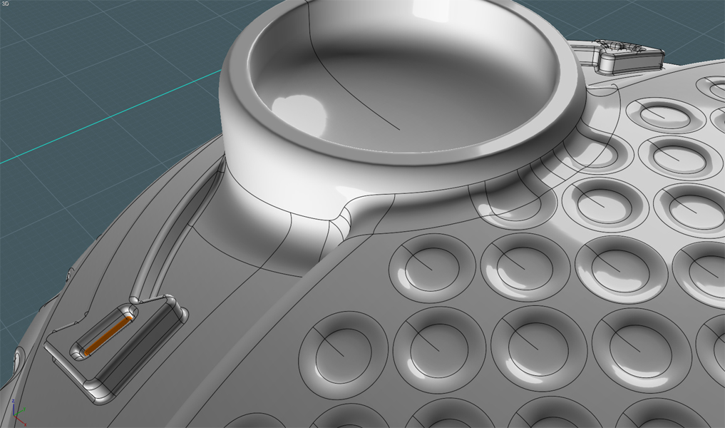
I can see several problems with the geometry that you have so far here though, which will make things really difficult to fillet - one right off the bat is that there is only a very teeny-tiny amount of space available in this area here:


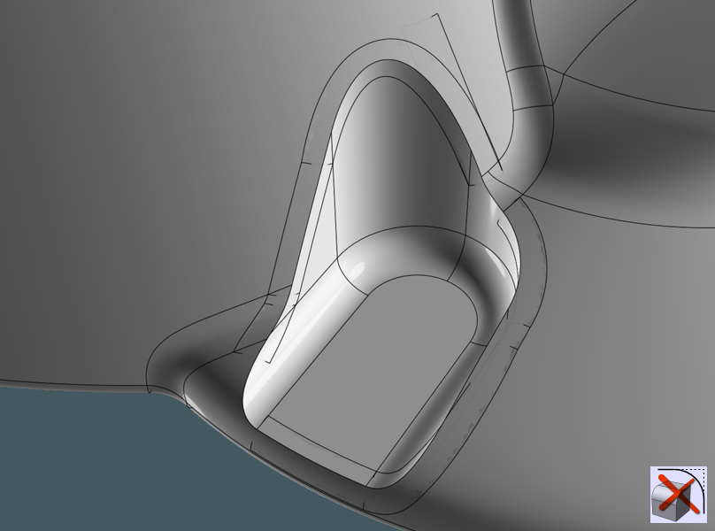
The way filleting works is that a fillet can only fit in the available room immediatley surrounding the edges that you are trying to fillet - it won't be able to cross over some nearby edge that is not actually part of the fillet chain where a fillet is trying to run along. So that means for example in your case here there would only be room to fit a super tiny sized fillet radius along that area before it collided with the nearby edge above it that you see highlighted in the second image.

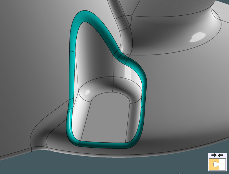
If you want to get fillets on something like this you need to have a construction configuration that allows enough room for fillets to fit between pieces, so basically you can't have edges from different pieces coming so extremely close to one another where the pieces intersect with each other.

There just is not much chance that stuff like that with narrowly grazing pieces is going to be filletable in MoI at least.

- Michael

  Reply Reply More Options
Post Options
Reply as PM Reply as PM
Print Print
Mark as unread Mark as unread
Relationship Relationship
IP Logged
 

Reply to All Reply to All


Show messages:  1-11  12-31  32-51  52-71  72-91  92-111  112-116