Majik Tutorial: Loop-Ended Handle
 1-20  21-24

Next
 From:  Mike K4ICY (MAJIKMIKE)
5072.1 
I realized that I never truly made a tutorial for some of the MoI objects posted in my list.

I thought I'd take a slightly different approach to the Loop-Ended Handle I created first.
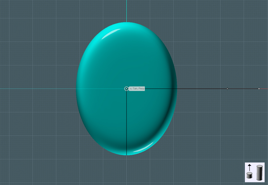
The big question: how to smoothly blend two solid shapes, like a ring and tube shape together.

First - I re-posted part of my earlier post to introduce the object challenge...


=====================================================================

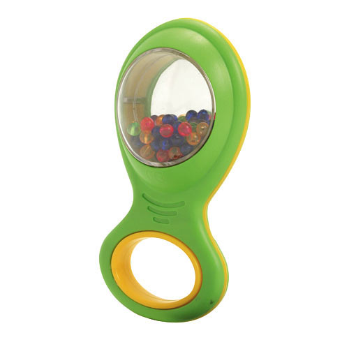
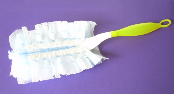
I took a look at the organic looking handle on top... The more I looked at it, the more I realized that it had some thought put into it.


I spent a little time the other day putting together this model to see if I could reproduce this shape in MoI.
I thought it would be simple, It's just a bulb shape that has a ring on it, but not only does the hanging ring "melt" into the handle grip, but it is tapered.
I noticed that everything was a generally a perfect tangent also. A perfect use for NURBS.
1) I swept a circle around a large circle to produce a torus shape. It was also tapered by moving a copy of the large ring on top and slanting it down on one side, using it as a Scaling Rail.
2) I cut out a chunk of the bottom of the ring to create a shape to merge to.
3) I created profiles for a network. I then Joined the ring and network mesh together.


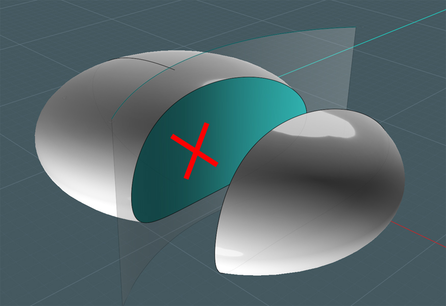
However. I still don't know a better way to make a whole and seamless creation.
You can see the irregularities in the connection between the two objects.


I tried different configurations of the Blend tool, but there are overriding tangents and a strange shape transition from a more rectangle shape to a circle along the neck.

Consequently, I did a Google search today for a pic of the handle, and actually found the guy that created this thing for the Swiffer company.
He lists that he uses Alias and Solid Works for his modeling. Alias is an Autodesk app - and one of a dozen or less devoted to one small aspect of 3D modeling.
My mind just boggled over the complexity of software solutions required to do this kind of work. Many apps duplicating the same features.


=====================================================================

If you'd like to follow along and break down the model, I provide it here: http://k4icy.50webs.com/tutorials/handle02.3dm

This exercise will deal mostly with simple surface-edge Blends.


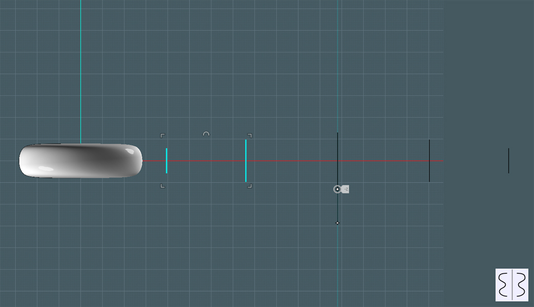
We need to make the ring shape.
Instead of Sweeping a circle along a larger oval, I'll construct it with an alternate method.

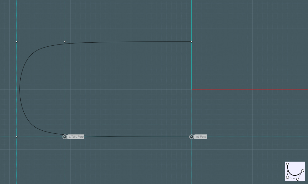
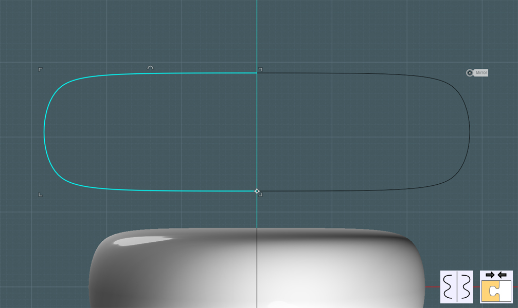
Make a profile using the Free-Form Curve - drag out some construction lines to help you keep the end points tangent:


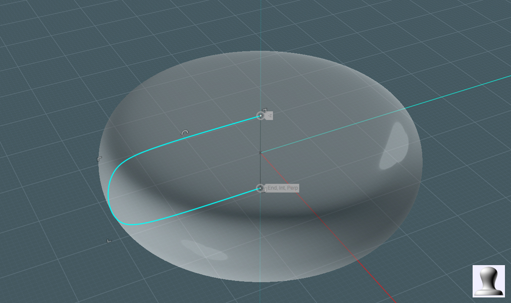
Revolve the profile to make a "cheese wheel" shape:


Use Scale-1D to elongate the wheel until it is more of an ellipse:


Don't throw that profile away! Make a mirror copy and join them to form a ring:


Make a few varying copies to create progressively sized profile rings:


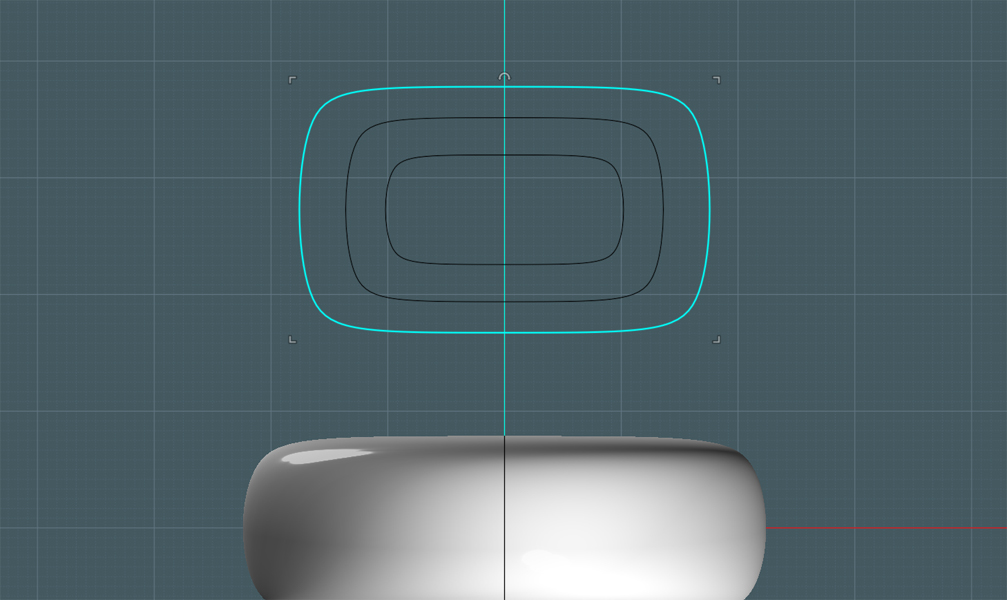
Space the rings out some:


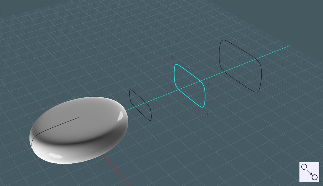
Use Mirror to make a copy of the two smaller ones, placing them on the other side of the larger one:


Select the rings in progression from front to back and perform a Loft function using the 'Smooth' mode:


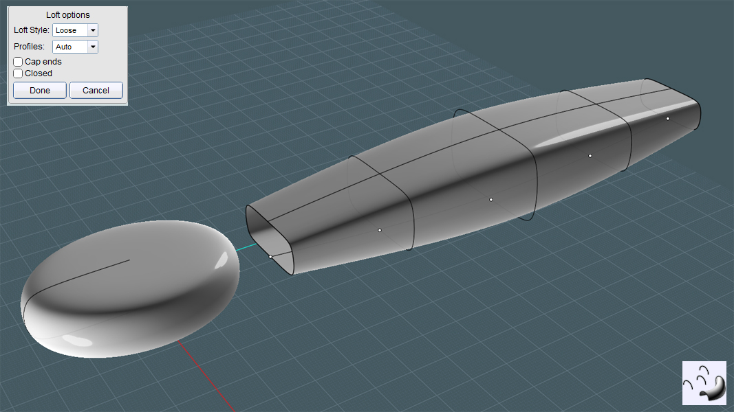
Tweaks along the way of any modeling process is a fact of life - I flipped the wheel shape over to match the splines:


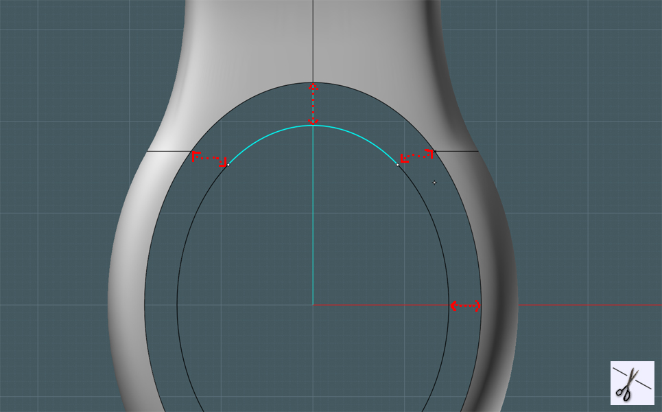
Since we need to blend the ring to the handle, we'll need to cut off what we don't need on the wheel:
Draw a line across the wheel closer to the back - take note of the position and angle of the edge you'll be creating.


Boolean Difference the line from the wheel. Discard the smaller part:


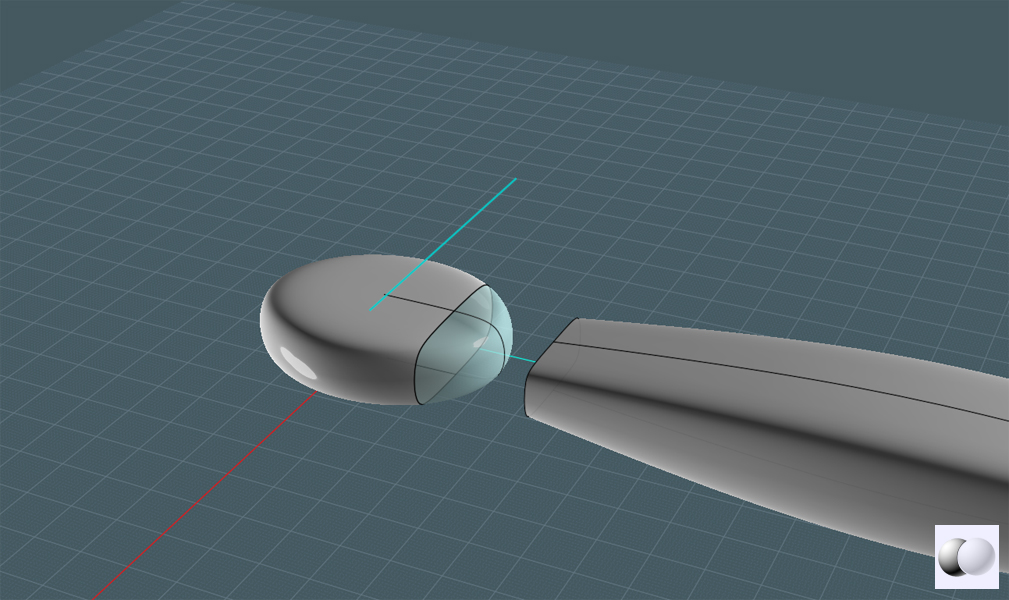
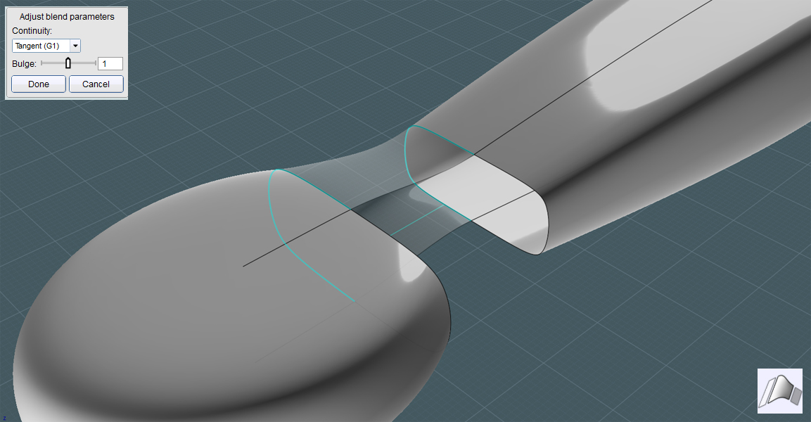
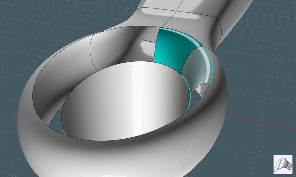
Use the Blend tool! Select the curves on the adjacent matching edges of each object.
If the edges don't match up, you'll have to either use the 'Merge' command on split surface edges or you'll have to use the 'Trim' function on to cause the edges of one object to match the edges on the other.
(shown later in this tutorial)


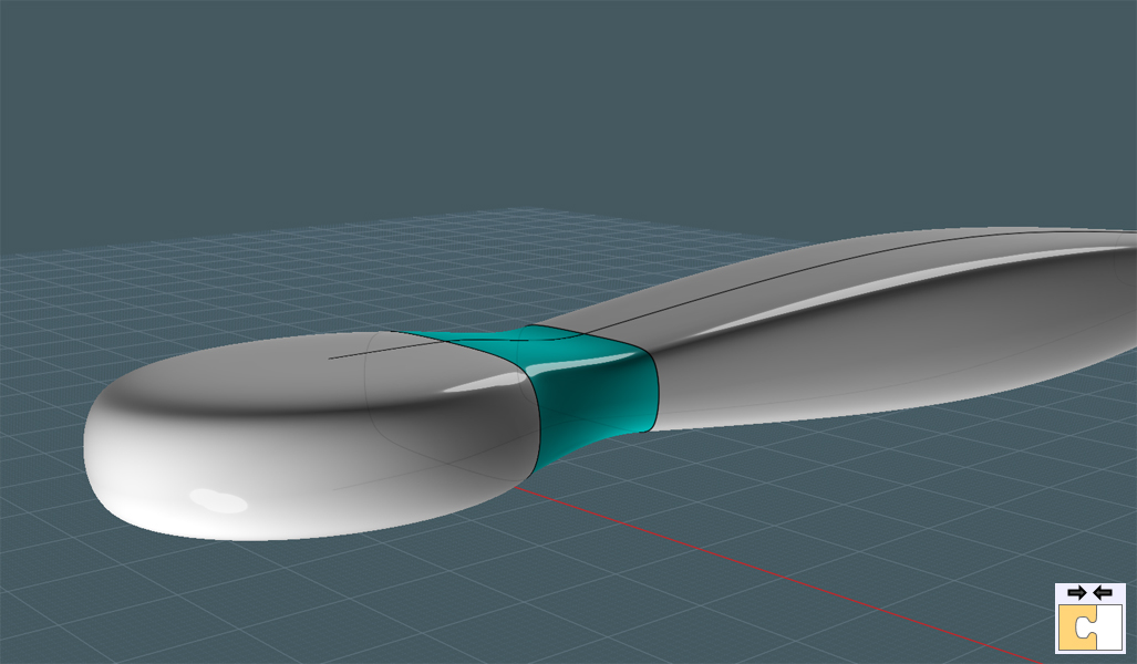
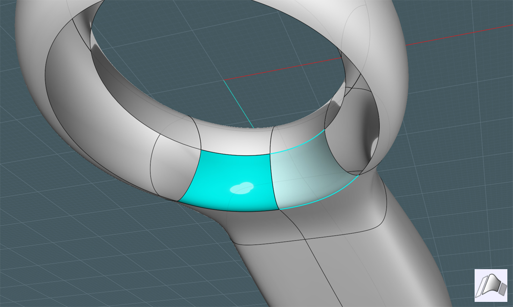
It's time to join the two main objects and the Blend surfaces to become one object:


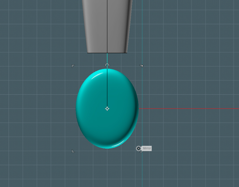
Draw a smaller ellipse that represents the mid-way point between the inside and outside boundaries of the ring shape:


Boolean Difference the smaller ellipse from the ring portion of the shape:


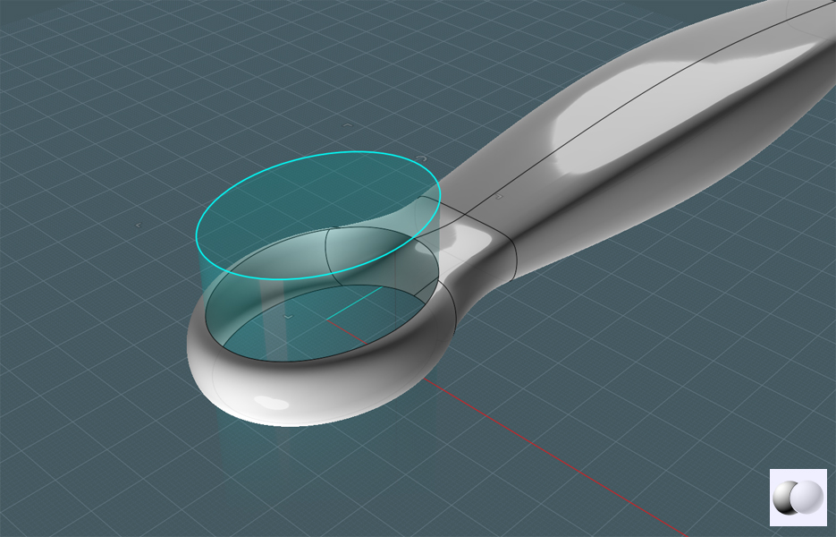
Re-size the ellipse to represent the inside boundary of the ring shape:


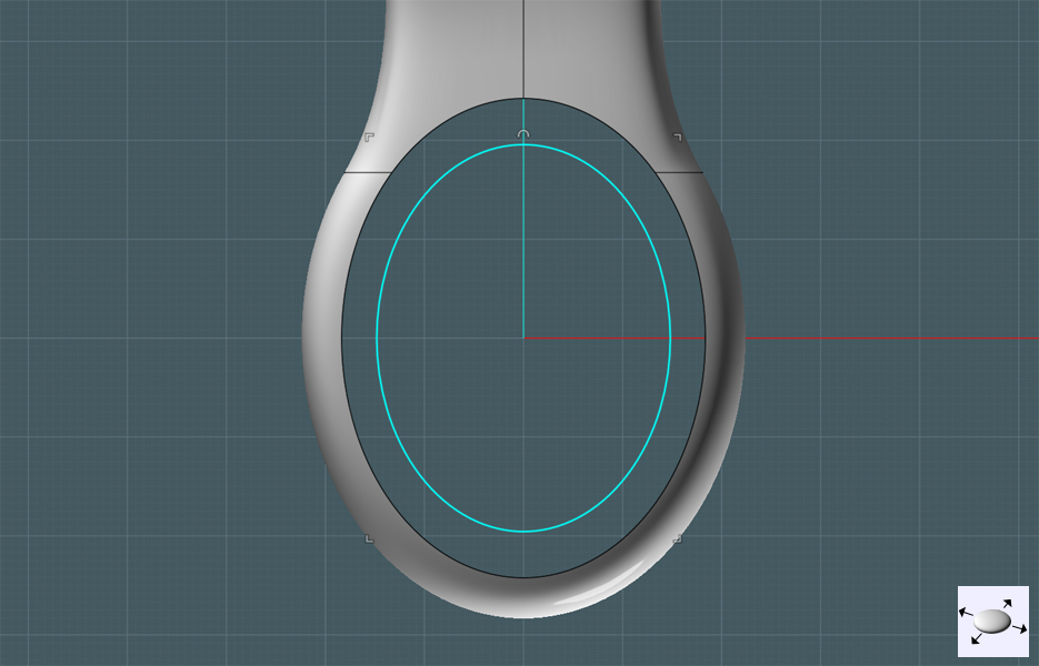
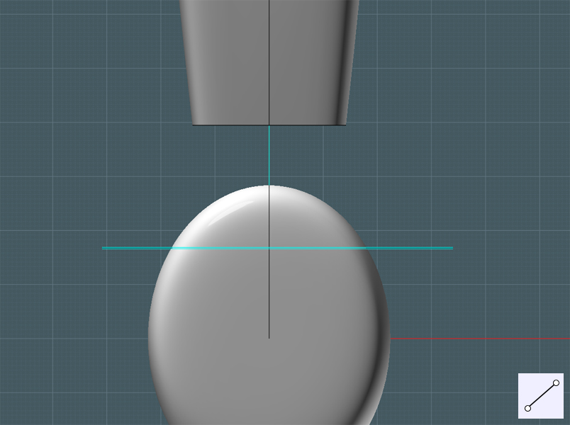
Move the small ellipse to the middle of the horizontal (Z) level of the ring shape:


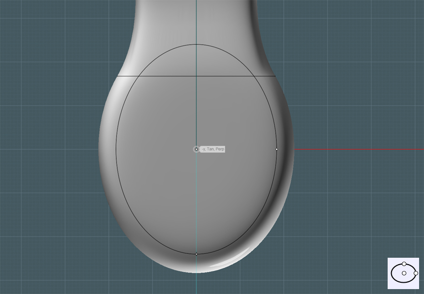
We need to have tangent edges by which to form Blend surfaces. For reference only, extrude the ellipse downwards:


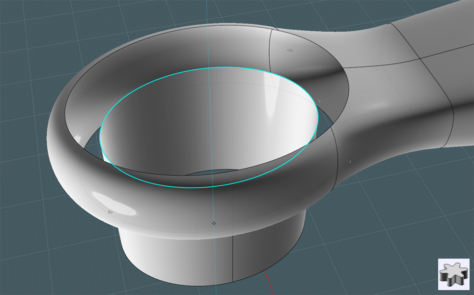
Again, the curves on the edges of both the extruded ellipse and the ring shape's cutout do not match completely.
Use either the 'Merge' command or the Trim function to 'pair' up the edges to Blend:


Blend the extruded ellipse edges and ring opening edges together:
Note - After you have Blended all the edges together, MoI will still let you temporarily change the size of the inside extruded ellipse,
which will re-build each blended surface.


Delete the extrusion - Now perform the same blend between the bottom opening of the ring shape and the previous extrusion edge of the first blends:


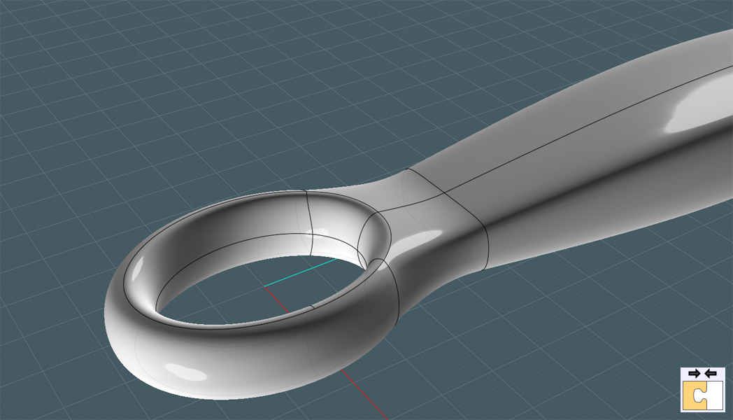
Join all edges together!
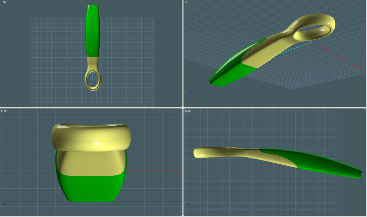
Now you have a ring-ended handle shape. But maybe you would like to give it a more ergonomic feel...


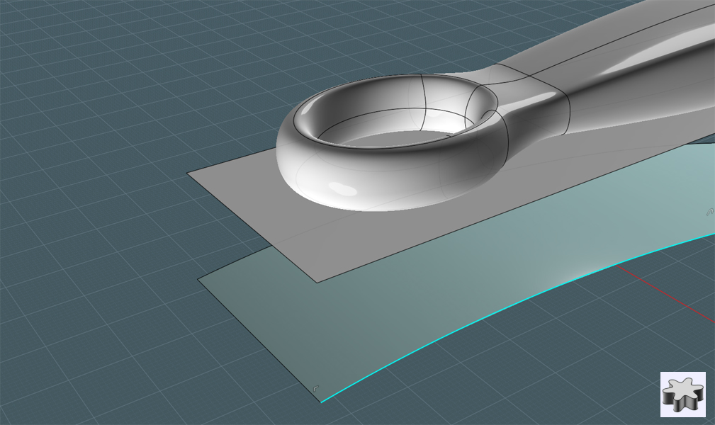
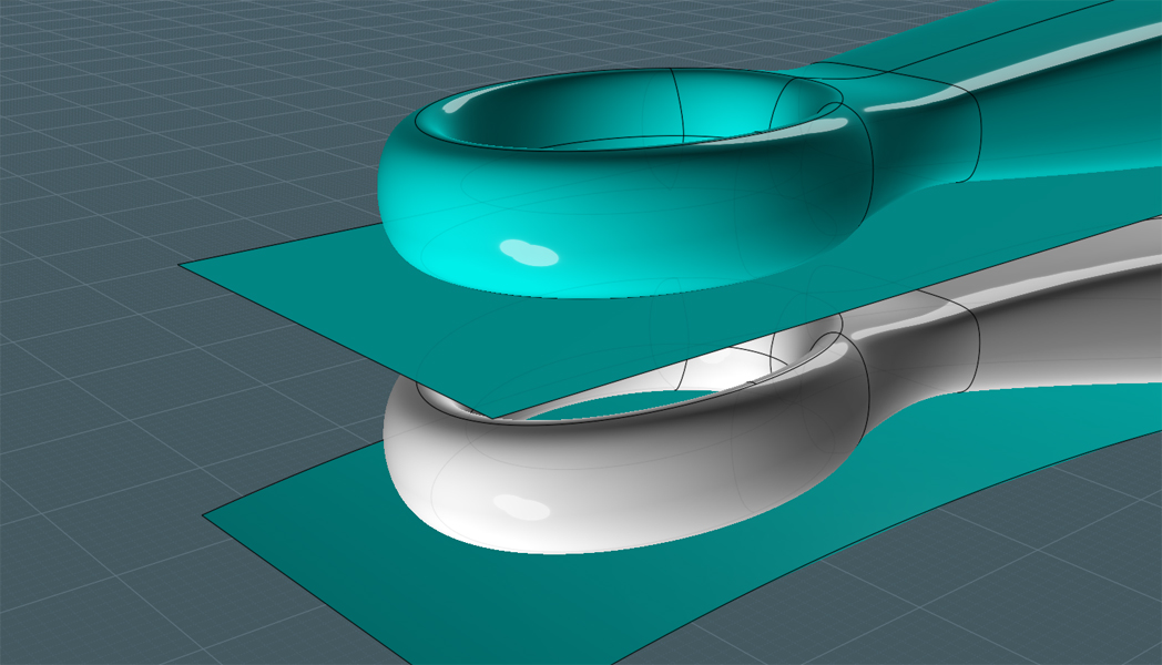
We will use the V3's Flow tool - Draw a Plane. Drawing a plane creates a surface where the real control point structure ends at the four corners you see. If you use Planar on a square the control points will be much larger than the shape you want and you will not end up with the Flow result you want.


You see where I'm going...

Draw a Free-Form curve or Arc to match the size of the reference Plane:


Extrude the curve to match the width of the Plane:


Use the Flow tool. Pay attention to the options given in the Flow dialog, they can alter the result:


Now do some additional trimming to add color and use this custom Loop-Ended Handle for you own projects:


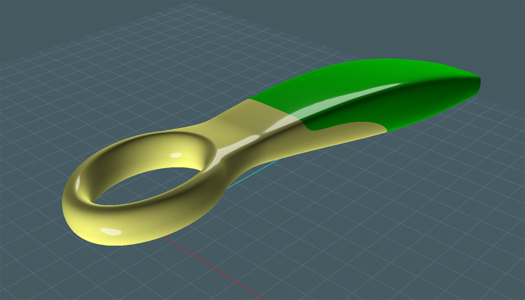
The Blend tool is not perfect and is really just a simple tool that tries it's best to match surface edges.
You may notice creases and aberrations in your resultant surface - but with some practice, you'll learn how to work around any disadvantages.

Enjoy!
  Reply Reply More Options
Post Options
Reply as PM Reply as PM
Print Print
Mark as unread Mark as unread
Relationship Relationship
IP Logged

Previous
Next
 From:  Ditto
5072.2 
Beautiful and elegant! Thanks!
  Reply Reply More Options
Post Options
Reply as PM Reply as PM
Print Print
Mark as unread Mark as unread
Relationship Relationship
IP Logged

Previous
Next
 From:  beanworks
5072.3 
dumb question: How do you get the transparent material?
  Reply Reply More Options
Post Options
Reply as PM Reply as PM
Print Print
Mark as unread Mark as unread
Relationship Relationship
IP Logged

Previous
Next
 From:  Mike K4ICY (MAJIKMIKE)
5072.4 In reply to 5072.3 
I knew someone was going to ask that!

Beanworks, I simply use PhotoShop to layer two separate screen-shots to create the 'transparent' appearance.

In my opinion, the more and more I use that effect, the more and more I wish there was an option in MoI to apply a transparency attribute to the object or its material.
It's a standard modeling procedure for me to grab objects that obscure my view and then to "Hide" them. The problem is that I often desire to still see the objects by some method for reference.

Michael, I'll consider adding it to the wish list, but a transparent attribute for objects shown the MoI display would prove valuable in applications requiring quick view of technical detail and sub-level illustration. I don't know if it's possible at all using DirectX, but it might be a snazzy feature.
  Reply Reply More Options
Post Options
Reply as PM Reply as PM
Print Print
Mark as unread Mark as unread
Relationship Relationship
IP Logged

Previous
Next
 From:  beanworks
5072.5 
ok, I'm glad I haven't overlooked some "transparent" feature in V3. I always use transparency when I work in 3dsMAX or solidworks, and I really really would like so see this feature in MoI. Regardless, MOI is still awesome
  Reply Reply More Options
Post Options
Reply as PM Reply as PM
Print Print
Mark as unread Mark as unread
Relationship Relationship
IP Logged

Previous
Next
 From:  Michael Gibson
5072.6 In reply to 5072.4 
Hi Mike, yup transparency in the display has been on the wishlist for quite some time.

It's not particularly easy to add - the way video cards work it's not possible to just set a single attribute and get proper object transparency, the polygons that you want to make transparent need to be sorted from back to front and sent to the video card to be drawn in that back to front order. So it's something that could easily have poor performance unless it is done quite carefully.

- Michael
  Reply Reply More Options
Post Options
Reply as PM Reply as PM
Print Print
Mark as unread Mark as unread
Relationship Relationship
IP Logged

Previous
Next
 From:  Mike K4ICY (MAJIKMIKE)
5072.7 In reply to 5072.6 
I see your point Michael. - Hallowed be your funky wisdom.
Sounds like a smoke maker for many video cards.

The same effect that occurs when I take a MoI file that flowed like glass at 1 degrees mesh setting at work, to then bring it to my home PC to find that the whole thing grinds to a halt at the 15 degrees setting. ;-)


That would have to be VERY optional.
  Reply Reply More Options
Post Options
Reply as PM Reply as PM
Print Print
Mark as unread Mark as unread
Relationship Relationship
IP Logged

Previous
Next
 From:  Rich_Art
5072.8 In reply to 5072.1 
That is really cool.. Thanks. Now I see your colorscheme I need to reinstall it again as well...

Peace,
Rich_Art. ;-)

| C4DLounge.eu | Our Dutch/Belgium C4D forum. |
  Reply Reply More Options
Post Options
Reply as PM Reply as PM
Print Print
Mark as unread Mark as unread
Relationship Relationship
IP Logged

Previous
Next
 From:  sandykoufax (JEONGHO_KIM)
5072.9 
Super cool tutorial.
Thank you so much!
  Reply Reply More Options
Post Options
Reply as PM Reply as PM
Print Print
Mark as unread Mark as unread
Relationship Relationship
IP Logged

Previous
Next
 From:  Frenchy Pilou (PILOU)
5072.10 
Cool tut!
But what is the use of this object ?
---
Pilou
Is beautiful that please without concept!
My Gallery
  Reply Reply More Options
Post Options
Reply as PM Reply as PM
Print Print
Mark as unread Mark as unread
Relationship Relationship
IP Logged

Previous
Next
 From:  Mike K4ICY (MAJIKMIKE)
5072.11 In reply to 5072.10 
> But what is the use of this object ?


Why Pilou, as the handle to the duster that cleans off your MoI work station!


Ce n'est pas agréable comme le chiffon à poussière ci-dessous:
Ouah! Bless the French. ;-)


But an interesting shape to reproduce, none the less.
  Reply Reply More Options
Post Options
Reply as PM Reply as PM
Print Print
Mark as unread Mark as unread
Relationship Relationship
IP Logged

Previous
Next
 From:  BurrMan
5072.12 In reply to 5072.11 
Oh, you had to go and do it.. The maid.. I suppose I'll visit this tute often, though never end up with a duster handle! :o
  Reply Reply More Options
Post Options
Reply as PM Reply as PM
Print Print
Mark as unread Mark as unread
Relationship Relationship
IP Logged

Previous
Next
 From:  Rich_Art
5072.13 In reply to 5072.11 
Mike, do you still have your scheme somewhere? the one that I have does not works very well with the v3 Beta..

Peace,
Rich_Art. ;-)

| C4DLounge.eu | Our Dutch/Belgium C4D forum. |
  Reply Reply More Options
Post Options
Reply as PM Reply as PM
Print Print
Mark as unread Mark as unread
Relationship Relationship
IP Logged

Previous
Next
 From:  Frenchy Pilou (PILOU)
5072.14 
Thx for the info!
I had believed that was a new sort of rattle :)
  Reply Reply More Options
Post Options
Reply as PM Reply as PM
Print Print
Mark as unread Mark as unread
Relationship Relationship
IP Logged

Previous
Next
 From:  Rich_Art
5072.15 In reply to 5072.14 
That is a cool object to model of course.. :-)

Peace,
Rich_Art. ;-)

| C4DLounge.eu | Our Dutch/Belgium C4D forum. |
  Reply Reply More Options
Post Options
Reply as PM Reply as PM
Print Print
Mark as unread Mark as unread
Relationship Relationship
IP Logged

Previous
Next
 From:  klickoff (RIKO)
5072.16 
Hi Magic! Thanks for a tutorials, as you have made transparent color surface?))))

My love MoI!!!
Attachments:

  Reply Reply More Options
Post Options
Reply as PM Reply as PM
Print Print
Mark as unread Mark as unread
Relationship Relationship
IP Logged

Previous
Next
 From:  stevecim
5072.17 In reply to 5072.1 
Hi All

I'm working through this tutorial, but am doing something wrong :( when I boolean Diff the line from the wheel and delete smaller section, I'm still left with a solid wheel, how do I convert a solid into a surface? sorry if this is a basic question :)


Never mind, selected the face and deleted it :(
  Reply Reply More Options
Post Options
Reply as PM Reply as PM
Print Print
Mark as unread Mark as unread
Relationship Relationship
IP Logged

Previous
Next
 From:  Mike K4ICY (MAJIKMIKE)
5072.18 In reply to 5072.17 
> I'm still left with a solid wheel,

Stevecim, cutting an object with a curve or line produces new "walls" that are really kind of extruded versions of the cut curve. Drill select into the cut object surface to select that new "wall", then delete it.
Hope this helped.

  Reply Reply More Options
Post Options
Reply as PM Reply as PM
Print Print
Mark as unread Mark as unread
Relationship Relationship
IP Logged

Previous
Next
 From:  Frenchy Pilou (PILOU)
5072.19 
<< I simply use PhotoShop to layer two separate screen-shots to create the 'transparent' appearance.

So you save 2 images ? (With the use of the Hide function)
1 the first object + Gride
2 the second object - Gride ? and give transparency :)

EDITED: 18 Apr 2012 by PILOU

  Reply Reply More Options
Post Options
Reply as PM Reply as PM
Print Print
Mark as unread Mark as unread
Relationship Relationship
IP Logged

Previous
Next
 From:  Mike K4ICY (MAJIKMIKE)
5072.20 In reply to 5072.13 
Hi Rich_Art,

> do you still have your scheme somewhere?


This is my lighting setting. It gives everything a nice 'plastic'-gloss look, and the highlight is a good surface continuity checker.

However, Rich_Art, since the V3 UI mechanism has been re-worked from V2, I'll have to wait to customize it until V3 is finalized.

Michael is using a new system that works with color and gradients to build the UI. You can already go to the right files and tweak those values, but I don't remember where.

You can see some of the UI color tweaks I use inside of this .ini file: http://k4icy.50webs.com/tutorials/moi_ini_EXAMPLE.txt


Hi Michael! Is there any way perhaps to change the map used for the specular highlight in the viewport? A couple of 'mock' florescent lights would be cool.
I have a feeling though, that it is hard-wired into the app.
  Reply Reply More Options
Post Options
Reply as PM Reply as PM
Print Print
Mark as unread Mark as unread
Relationship Relationship
IP Logged
 

Reply to All Reply to All


Show messages:  1-20  21-24