please, need help again!
 1-20  21-23

Next
 From:  mike (MIOHN)
4997.1 
Hi,

have no idear, why I can't get a fillet around selected edge.

I "command" merged thousand times!
I "jointed" thousand times!
I "boolean" merged thousand times!

I tried fillets-values between 0.0001, 0.001, 0.01, 0.1 and 1

But still no fillet.
And still I can select seperate faces.
Why does this not come together as one object?

thanks
Mike
Attachments:

  Reply Reply More Options
Post Options
Reply as PM Reply as PM
Print Print
Mark as unread Mark as unread
Relationship Relationship
IP Logged

Previous
Next
 From:  SteveMacc (STEVEH)
4997.2 
I think the fillet problem is linked to the chamfers you have on two of the edges. Michael will no doubt give you a full analysis.
  Reply Reply More Options
Post Options
Reply as PM Reply as PM
Print Print
Mark as unread Mark as unread
Relationship Relationship
IP Logged

Previous
Next
 From:  niko (NICKP100)
4997.3 
It is a difficult fillet because of the angle that will require a non-traditional method and multiple blends.I started doing it here just to illustrate that it can be done with MOI but not with the fillet command..
Image Attachments:
Size: 121.8 KB, Downloaded: 36 times, Dimensions: 1163x707px
  Reply Reply More Options
Post Options
Reply as PM Reply as PM
Print Print
Mark as unread Mark as unread
Relationship Relationship
IP Logged

Previous
Next
 From:  Paolo (PAOLOLOBBIA)
4997.4 In reply to 4997.1 
Hi Mike,


I noticed that your model isn't flat on the underside when you look in the right view.
In the top view,the right side is larger than the left side.
Is this intended.

Here's my version which is symmetrical, radius 0.05,shape circular:
Attachments:

  Reply Reply More Options
Post Options
Reply as PM Reply as PM
Print Print
Mark as unread Mark as unread
Relationship Relationship
IP Logged

Previous
Next
 From:  Michael Gibson
4997.5 In reply to 4997.1 
Hi Mike, you've got a variety of things in there that make things difficult for filleting.

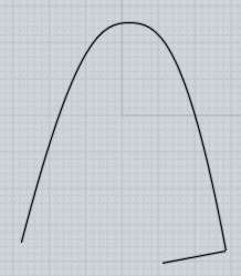
Here the edge that you're trying to fillet goes around a tight bend:


The tightness of the bend there will greatly limit the size of fillet that will actually fit going around that bend before it starts to collide into itself. If you have a fillet that is larger in radius than the bend that it goes around, it ends up with an effect like this:


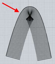
So you're probably better off leaving that edge as sharp initially and actually fillet it as well instead of trying to draw it in as a tight rounded edge in the initial profile.

Also see here for some previous discussion on this:
http://moi3d.com/forum/index.php?webtag=MOI&msg=4773.7


So anyway, that's one kind of problem area of your model.


Another thing that tends to cause problems with filleting is when you have 2 faces that are coplanar where they touch, it's better for planar areas to be one single big plane instead of fragmented into different surfaces. You've got an area like that at the bottom here:


That's not good for filleting - instead of that you should instead have the planar area be one large plane, and the rounded portion should be a separate surface. It's probably easiest to model this edge as just totally sharp initially and then put a large radius fillet on it to round it off:


So you would want this bottom part to look more like this with one single large plane in here:


Just in general you've kind of drawn in some curved areas in your initial profile that would have probably been better off left as sharp junctures to start with and then rounded off with filleting instead.


Then you've still got another problematic area for filleting in this corner region here:


That juncture is going to be difficult for the filleter to handle with a corner patch.

It's particularly difficult because this area here seems to be at a very slight slope where it comes to meet the plane on the left side:


Filleting does not generally like to handle pieces that come together at a shallow angle, it's better for surfaces to be either totally smooth where they touch or more distinctly sharp where they touch rather than coming to something like a 1-5 angular degree difference where they touch. That kind of slight angular deviation tends to force the filleter to attempt to make little tiny slivery junctures between pieces and little slivery pieces can tend to confuse the whole process.


So you probably want to eliminate this edge here:


You'd either want the top surface to be all one large surface instead of stopping there, or you would want to flatten out this area here:


So that there was a large plane on top there that ended something like over here instead:


So anyway I hope this helps give you some explanation on the kinds of things that makes things difficult for filleting, you've got several things in here that are like that.

A few general tips are to not draw in any really sharp bends in your initial profile - make things like that sharp initially and then you can round it off with a fillet at the same time that you are filleting the outer edge. It's easier for the filleter to deal with making a corner juncture between fillets in places like that rather than making it try to construct a fillet that actually tries to navigate around the tight bend where it wants to be building a fillet surface.

Then the other thing is to make planar areas of your model to be more distinct single planes - again probably in some areas where you've got a large flat-ish area you want that area to be just a simple line in your profile curve that has a sharp juncture with its surrounding area rather than having a kind of nearly smooth sort of juncture between pieces.

So overall if you kind of place some more sharp edges in your initial profile it would actually help out the whole process.

- Michael

  Reply Reply More Options
Post Options
Reply as PM Reply as PM
Print Print
Mark as unread Mark as unread
Relationship Relationship
IP Logged

Previous
Next
 From:  mike (MIOHN)
4997.6 
Hi Poalo,

no, was not intended. Maybe a mistake.
I'm pretty new to MOI .

But I don't understand what you mean with "boolean difference" in your file
and how did you get the bevel/fillet on the side? I also tried 0.05 and lots of other values .....

regards
MIke
  Reply Reply More Options
Post Options
Reply as PM Reply as PM
Print Print
Mark as unread Mark as unread
Relationship Relationship
IP Logged

Previous
Next
 From:  Michael Gibson
4997.7 In reply to 4997.6 
Hi Mike, looks like we posted the last messages at the same time - I just want to make sure you notice that I posted a large reply above with some details about problem areas of the model and some description on how you would better structure it to be more fillet friendly.

- Michael
  Reply Reply More Options
Post Options
Reply as PM Reply as PM
Print Print
Mark as unread Mark as unread
Relationship Relationship
IP Logged

Previous
Next
 From:  Michael Gibson
4997.8 In reply to 4997.4 
Hi Mike, and yeah like Paolo mentions above having things on slightly different levels from one another is not helping things either.

So for example in the right-side view of your model here:


- Michael

  Reply Reply More Options
Post Options
Reply as PM Reply as PM
Print Print
Mark as unread Mark as unread
Relationship Relationship
IP Logged

Previous
Next
 From:  mike (MIOHN)
4997.9 
Hi Michael,

thanks for your detailed comment.

Well, still pretty new to MOI and therefore
I'm still making lot of mistakes.

I also saw the problem of thight corners and nonplanar surfaces, but I don't know
how to fix the areas you adressed. And I thought, even on thight coners, that a
value of 0.0001 would give at least a very very little fillet.

I think, the way I modeled this was completely wrong.
So for this kind of object, which way would be the best to model?

(Its just a phantasy object which has not to be accurate and which shape
grows from step to step.)

regards
MIke
  Reply Reply More Options
Post Options
Reply as PM Reply as PM
Print Print
Mark as unread Mark as unread
Relationship Relationship
IP Logged

Previous
Next
 From:  mike (MIOHN)
4997.10 
Hi Paolo,

now I understood, what you meant with boolean difference.

thanks
Mike
  Reply Reply More Options
Post Options
Reply as PM Reply as PM
Print Print
Mark as unread Mark as unread
Relationship Relationship
IP Logged

Previous
Next
 From:  Michael Gibson
4997.11 In reply to 4997.1 
Basically for filleting to be happy you'll either need for pieces to be all one big surface or otherwise to have more separation between areas that are planar.

Right now you've kind of got a half of both ways, you've got most of it as one big surface but then a kind of akward separation kind of right in the middle.

It looks like you started with this shape here:


Then this area here was kind of tacked on separately:


That's left you with some separation between those pieces with edges in these areas here:


If you wanted to do it with all one big surface, then you would want to instead draw in the initial side profile where it was extended some more to the left side more like this:


Then you would cut that with a curve from the top view to slice away material to form the end part instead of kind of gluing it on afterwards:


That kind of approach where you model a larger block and then carve off pieces can tend to make a better end result on things that are supposed to look like they are just one single smooth piece.

If you look at Paolo's example you can see that's how he set it up.

- Michael

  Reply Reply More Options
Post Options
Reply as PM Reply as PM
Print Print
Mark as unread Mark as unread
Relationship Relationship
IP Logged

Previous
Next
 From:  Paolo (PAOLOLOBBIA)
4997.12 In reply to 4997.6 
Hi mike,

Click the extrude command and select the vertical shape.
Activate Cap ends plus Both sides and extrude to the desired lenght.

Click boolean difference and select the solid.
On the question "select objects to subtract" select the horizontal curve and right click.
Delete the unwanted shape.

I noticed that fillet was inconsistent so i uploaded a modification.
In this case i extended the horizontal curve a bid to make sure that the cut turns out clean.
It's a bit difficult to explain but nurbs are al about mathematics and a bit intolerant to human errors.
Attachments:

  Reply Reply More Options
Post Options
Reply as PM Reply as PM
Print Print
Mark as unread Mark as unread
Relationship Relationship
IP Logged

Previous
Next
 From:  Michael Gibson
4997.13 In reply to 4997.9 
Hi Mike,

> I also saw the problem of thight corners and nonplanar
> surfaces, but I don't know how to fix the areas you adressed.

You'll pretty much have to reconstruct the object over again.

There are basically 2 different styles that you could approach it - you would either want to make it more segmented with some more sharp edges in your initial profile or otherwise actually make it more all one single large piece.

Check out Paolo's attached file for the "single piece" method - there you'll see that he's drawn in the side profile in such a way that it is extended more to the left and then the rounded area on the left side is produced by carving off some material from a curve that is flat in the Top view. That basically avoids having an extra edge thrown right in to the middle of where you want to have filleted and anything that simplifies the edge structure of your object (like reduces the number of edges meeting up at a single shared point) can also make things easier for filleting.


> And I thought, even on thight coners, that a
> value of 0.0001 would give at least a very very little fillet.

That would normally be correct if that was the only problem area, but the other problematic juncture areas that I mentioned are also a factor in your case here.

- Michael
  Reply Reply More Options
Post Options
Reply as PM Reply as PM
Print Print
Mark as unread Mark as unread
Relationship Relationship
IP Logged

Previous
Next
 From:  mike (MIOHN)
4997.14 
o.k. "Boolean Difference" is the magic!
Did a good progress with the tips you all gave me!

The main mistake I was doing all the time, was, that I tried
to get these shapes with curves/profiles and the "trim" command.

When I use "boolean difference" instead (thought this only works with "solid" objects)
I can make fillets without problems, because doing this was I end up with proper closed shapes.
What also helped much, was the tip to make the profiles harder first and get the rouded corners
with fillet later!

thanks so far!
Mike
  Reply Reply More Options
Post Options
Reply as PM Reply as PM
Print Print
Mark as unread Mark as unread
Relationship Relationship
IP Logged

Previous
Next
 From:  Michael Gibson
4997.15 In reply to 4997.14 
Hi Mike, yeah so boolean difference is kind of like an automated "batch mode" of Trimming.

It basically does the same basic kind of job as trimming but in fewer steps because it keeps things as solids so any 2D curves that you use to cut the solid will leave behind their "side walls" and so you won't have to do any extra work to construct those separately.

So it can often save quite a bit of time overall if you work more with solids and try to use booleans when possible to do most of the work rather than only using Trim - Trim is kind of more "low level" and can help with some more difficult situations like when you're trying to repair a surface or replace just one small area of an object or things like that.

But for the basic main construction work try to stay more in the area of booleans and solids, it just tends to go quicker.

- Michael
  Reply Reply More Options
Post Options
Reply as PM Reply as PM
Print Print
Mark as unread Mark as unread
Relationship Relationship
IP Logged

Previous
Next
 From:  mike (MIOHN)
4997.16 
Hi Michael,

hehe, our inputs are overlapping all the time.

I exactly did it in the order you descriped.
But I understand now how to do it. (what Paolo showed in his file)


But what, if I'm building up and the work goes further and further
and then later (maybe too late) I decite, that I want to add an extra shape or part
somewhere.
How do I manage that?
Does it mean, that I (better) have to rebuild the whole object at the end?

thanks
Mike
  Reply Reply More Options
Post Options
Reply as PM Reply as PM
Print Print
Mark as unread Mark as unread
Relationship Relationship
IP Logged

Previous
Next
 From:  mike (MIOHN)
4997.17 
by the way ...

Where I also have big problems is, to cutout/engrave Typo
on curved surfaces.

In this case I think I have to use "timm"
So what I#M doing is:
1. selecting object
2. select the typo-curve
3. trimm
4. offset - inset or shell
and then ...
5. problem

Should I do this also via "boolean"?

thanks
Mike
  Reply Reply More Options
Post Options
Reply as PM Reply as PM
Print Print
Mark as unread Mark as unread
Relationship Relationship
IP Logged

Previous
Next
 From:  Michael Gibson
4997.18 In reply to 4997.16 
Hi Mike,

> But what, if I'm building up and the work goes further and
> further and then later (maybe too late) I decite, that I want
> to add an extra shape or part somewhere.
> How do I manage that?

Well, a lot of these tips here in this thread are about how to do things better for filleting.

Do you mean that you would decide to add another part to the object after you have done some filleting on it or before you did the filleting?

If you wanted to do it after filleting, then you may have to reconstruct that area of the object. But it depends on the particular case.

If you think you might add more parts to an object later, it would probably be better to use the "more segmented" type approach where you had things more separated out so that stuff like planar areas of your shape was one separate plane surface instead of it all as one big single surface. That approach would lend itself better to adding more pieces later.


> Does it mean, that I (better) have to rebuild the
> whole object at the end?

It could mean that but it depends on the particular situation...

- Michael
  Reply Reply More Options
Post Options
Reply as PM Reply as PM
Print Print
Mark as unread Mark as unread
Relationship Relationship
IP Logged

Previous
Next
 From:  Michael Gibson
4997.19 In reply to 4997.17 
Hi Mike,

> Where I also have big problems is, to cutout/engrave Typo
> on curved surfaces.

Do you have an example file that you could post so I could see one of these situations?


> Should I do this also via "boolean"?

Yeah usually you would also use a boolean for that - finish building any pieces of your curved surface so that it is a solid volume and not just a single surface and then create your text as solids. Then select your base piece and run boolean difference, and then select the text as the cutting objects and it will cut into it and leave an engraved result.

I'm not quite sure why you're referring to offset and inset for that - are you trying to do some kind of special effect on the text or something like that?

- Michael
  Reply Reply More Options
Post Options
Reply as PM Reply as PM
Print Print
Mark as unread Mark as unread
Relationship Relationship
IP Logged

Previous
Next
 From:  mike (MIOHN)
4997.20 
I'm not quite sure why you're referring to offset and inset for that - are you trying to do some kind of special effect on the text or something like that?

Because I don't know it better. I thought, thats the way to do it.

I'm comming from the Polygon/Subdivision-Modelling and have very little experience
in Nurbs-Modelling.
When I get more time I should go through the manual in detail.
Especialy for learning which functions to use for which operations.

But thanks very much for your support!

regards
Mike
  Reply Reply More Options
Post Options
Reply as PM Reply as PM
Print Print
Mark as unread Mark as unread
Relationship Relationship
IP Logged
 

Reply to All Reply to All


Show messages:  1-20  21-23